Editor Interface
3. EDITOR INTERFACE
The Proveris® OEE editor interface is designed to help users structure and manage production data efficiently, featuring a user-friendly and accessible layout. Its modern design streamlines interaction and makes data modeling more intuitive.
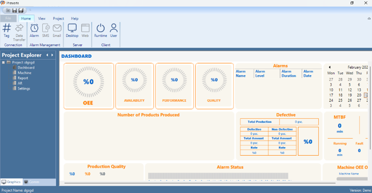
Figure 1 – Editor Interface
On the left, the Project Explorer displays a list of project modules such as Dashboard, Machine, Report, AR, and Settings. When a user selects a module from this panel, the corresponding content is displayed in the central screen.
The top ribbon menu offers access to essential functions such as tag definitions, data transfer, alarm management, and SMS/Email integrations. It also includes controls for server/client connections and starting the runtime environment. The interface is designed to be clean and modular, enabling users to build their projects quickly and intuitively.
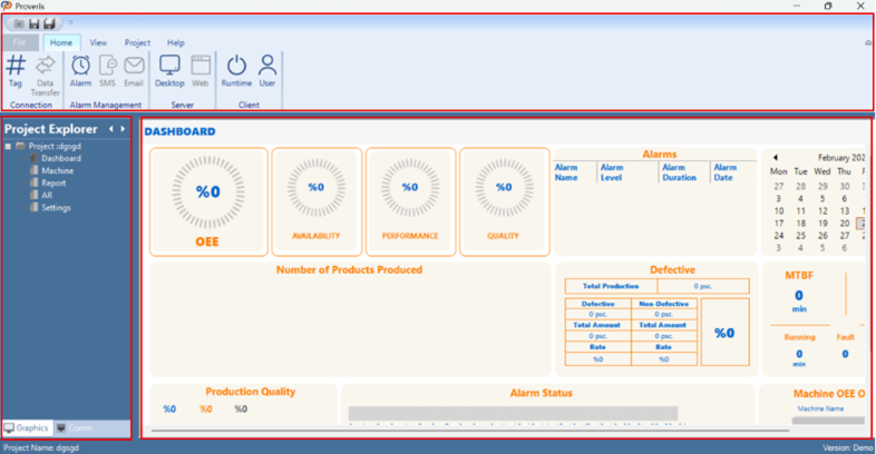
Figure 2 – Interface Controls
Detailed explanations of the editor interface controls are provided in the following sections.
3.1 Toolbar
The toolbar is an essential tool that provides quick access to the program's core functions. It includes main categories such as "File", "Home", "View,", “Project” and "Help" offering options for file creation, saving, project tools, views, and support.
Effective use of the menu bar contributes to the program's efficient operation and enhances the user experience. The options in the Proveris® OEE interface menu bar are listed below:
File | Home | View | Project | Help |
Table 1 – Toolbar
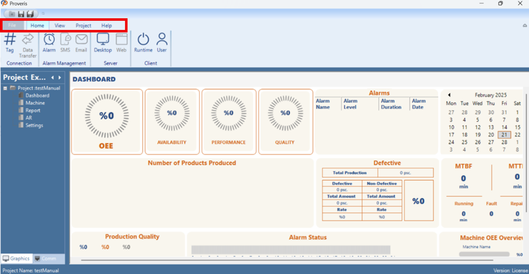
Figure 3 – Menu Bar
All the options in the menu bar are explained in detail in the following sections.
3.1.1 File
In Proveris® OEE, the "File" tab in the interface is used for project edits and file operations.
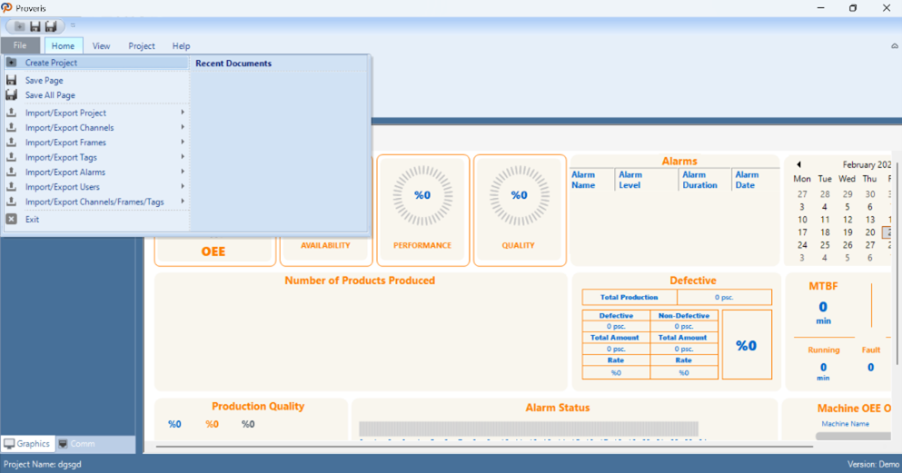
Figure 4 – File
File | Description |
Create project | Creates a new project. |
Save page | Saves the current page in the project. |
Save All Page | Saves all pages in the project. |
Import/Export project | Command for importing and exporting the project file. |
Import/Export channels | Command for importing and exporting channel data. |
Import/Export frames | Command for importing and exporting frame data. |
Import/Export tags | Command for importing and exporting tag data. |
Import/Export alarms | Command for importing and exporting alarm data. |
Import/Export users | Command for importing and exporting user information. |
Import/Export channels/frames/tags | Command for importing and exporting channel, frame, and tag data |
Exit | Exits the application. |
Table 2 – File Commands
*Note: (The files to be added must be in .xlsx format.)
3.1.2 Home
The "Home" tab allows users to add and configure various system components and settings. This tab includes options for establishing connections, managing alarms, setting up server and client.
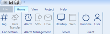
Figure 5 – Home Tab
Connection
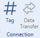
Figure 6 – Connection Toolbar
Tag Editor: The "Tag Editor" is used to define and configure tags, which represent data points within the system. Users can edit tag properties and set parameters to align with system requirements.
Data Transfer Editor: The "Data Transfer Editor" facilitates the configuration of data transfer settings between systems or components. Users can define data protocols and ensure smooth communication.
Alarm Management
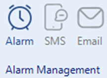
Figure 7 – Alarm Management Toolbar
Alarm Editor: The "Alarm Editor" is used to define and customize alarm settings, including the conditions that trigger alarms and the actions that follow.
SMS Editor: The "SMS Editor" allows users to configure SMS notifications for alarm events. Users can define SMS templates and specify recipient details for alerting purposes.
Email Editor: The "Email Editor" enables users to set up email notifications for alarms or events. It allows customization of email templates and the configuration of recipient information.
Server
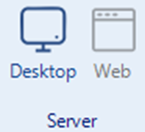
Figure 8 – Server Toolbar
Desktop: The "Server" function starts the server component of the OEE system. It initializes and activates the server, which manages communication, data processing, and connected devices. The server acts as the central hub, collecting and transmitting real-time data from devices and sensors to other system components, such as client applications. It is essential for establishing and maintaining the OEE system's communication infrastructure.
Web: The "Web" option starts the web server, enabling access to the system’s web interface for remote monitoring and control.
Client
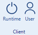
Figure 9 – Client Toolbar
Runtime: The "Client" function starts the client component of the OEE system. It launches the client interface, connects to the server, and allows users to view real-time data, interact with the system.The client serves as the user interface, enabling data visualization, monitoring, while communicating with the server to retrieve and display processed data.
User Editor: The "User Editor" allows the creation and management of user accounts and access rights. Users can define roles, permissions, and security settings for system access.
3.1.3 View
Adjustments can be made in the windows located on the left side of the interface. You can hide or show the windows depending on the project. The view settings are managed from here
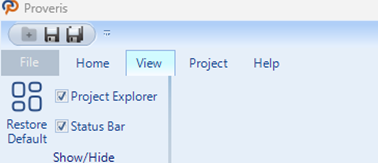
Figure 10 – View Tab
.
Project Explorer
The Project Explorer is a panel in Proveris® OEE that displays and manages the entire project structure.
The Project Explorer CheckBox controls the visibility of the Project Explorer panel. When checked, the Project Explorer is displayed; when unchecked, it is hidden.
1. Graphics
Enables the viewing of project parts.
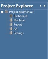
Figure 11 – Project Explorer Graphics Menu
2. Communication:
Allows access to all details related to channels, frames, tags, and other communication elements.
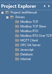
Figure 12 – Project Explorer Communication Menu
Status Bar
The Status Bar is located at the bottom of the Proveris® OEE interface and displays the project name and license status.
The Status Bar CheckBox controls the visibility of the Project Explorer panel. When checked, the Project Explorer is displayed; when unchecked, it is hidden.
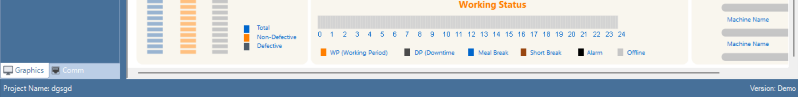
Figure 13 – Status Bar
3.1.4 Project
The "Project" tab provides essential tools for managing and configuring projects within the software. It includes options for importing, exporting, and editing project files, as well as adjusting client and system settings. This section is designed to streamline project workflows and enhance user efficiency.
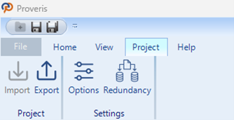
Figure 14 – Project Tab
Project
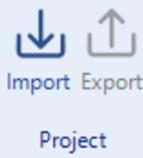
Figure 15 – Project Toolbar
Import: The "Import" function allows users to bring external project files into the software. It supports various file formats, enabling the integration of pre-existing data and configurations into the current project.
Export: The "Export" option enables users to save project files in different formats for external use. This function facilitates sharing, backup, or transferring project data to other systems while maintaining compatibility.
Settings
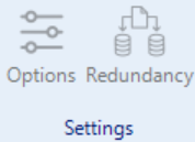
Figure 16 – Settings Toolbar
Client: The "Client" settings allow for configuration of client-side parameters and connections. Users can manage client devices, adjust connection settings, and optimize interactions between the client and the system.
Redundancy:
In OEE systems, redundancy refers to having backups of critical components to ensure continuous and reliable service. This includes software, data, and communication redundancy. Software redundancy takes over during failures, while data redundancy prevents data loss. Communication redundancy provides alternative solutions for communication issues.
In redundant systems, there are primary and secondary servers. When a disruption occurs in the connection of the primary server, the secondary server automatically takes over to ensure uninterrupted operation of the system.
For redundant operation to function effectively, the software version and project files on both servers must be identical.
Primary Server Setup
First, in the OEE system where the primary server is installed, click on "Redundancy" in the Tools tab. In the opened window, select the primary server. Then, enter the "Port" information for communication and confirm the settings.
Secondary Server Setup
In the OEE system where the secondary server is installed, click on "Redundancy" in the Tools tab. In the opened window, select the secondary server and enter the "Port" information for communication. Then, enter the IP address of the primary server and specify the timeout duration for the secondary server to take over, and confirm the settings.
3.1.5 Help
The "Help" tab provides users with access to various support resources and documentation. It includes options for getting assistance, reviewing examples, accessing product-related information, and understanding licensing terms.
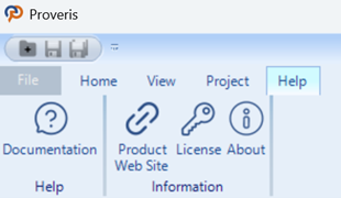
Figure 17 – Help Tab
Help
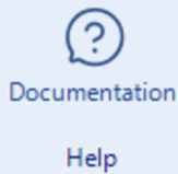
Figure 18 – Help Toolbar
Help: The "Help" option directs users to the software's built-in support and documentation. It provides detailed guidance on using features, troubleshooting issues, and accessing additional resources to enhance the user experience.
Information
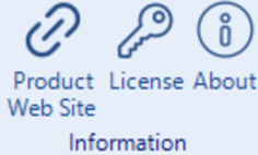
Figure 19 – Information Toolbar
Product Website: The "Product Website" link takes users to the official product website. Here, they can find more information about features, updates, system requirements, and other resources to better understand and utilize the software.
License: The "License" option displays the terms and conditions of the software license. Users can review the legal agreements, including usage rights, restrictions, and other important legal information regarding the software.
About: The "About" section provides detailed information about the software version, copyright details, and the development team. It also includes contact information for support and feedback.
3.2 USER EDITOR
The user editor is used to manage the roles and access rights of users in the system. It allows adding new users, editing existing users, or deleting users.
The editor manages page and alarm authorizations, ensuring that users can only access the information necessary for their tasks. Monitoring user activities enhances system security.
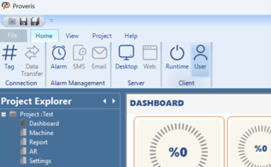
Figure 20 – User Editor
Creating a User Account
In the editor window, the "Created Users" section contains the registered user information. User addition and deletion operations are performed in this area. The general appearance of the editor is shown in the image below.
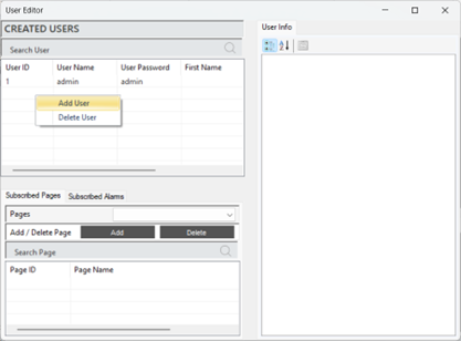
Figure 21 – Creating a User
To create a new user, right-click and select the option to add a user. Enter the username, password, and email information to add the user.
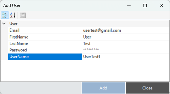
Figure 22 – Creating a User
Editing a User Account
To access and edit user information, the relevant user is selected. All details about the user are displayed in the "User Info" section of the panel. Updates can be made to all information, such as password and email, as needed.
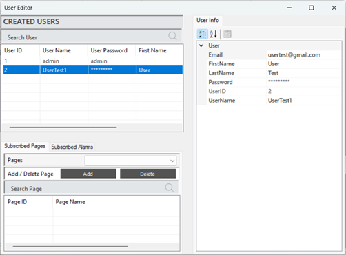
Figure 23 – User Info
The descriptions of the parameters related to the user account are provided in the table below.
“Email” | User's email contact information |
“First Name” | User's first name |
“Last Name” | User's last name |
“Password” | Password information to protect the user's account |
“User ID” | A unique identification number assigned to each user in the system |
“User Name” | User's login name in the system |
Table 3 – User Parameters
Page Authorization
Page authorization refers to the adjustments made to manage users access rights to specific pages. This process ensures that only authorized users can access the necessary information, aiming to maintain system security.
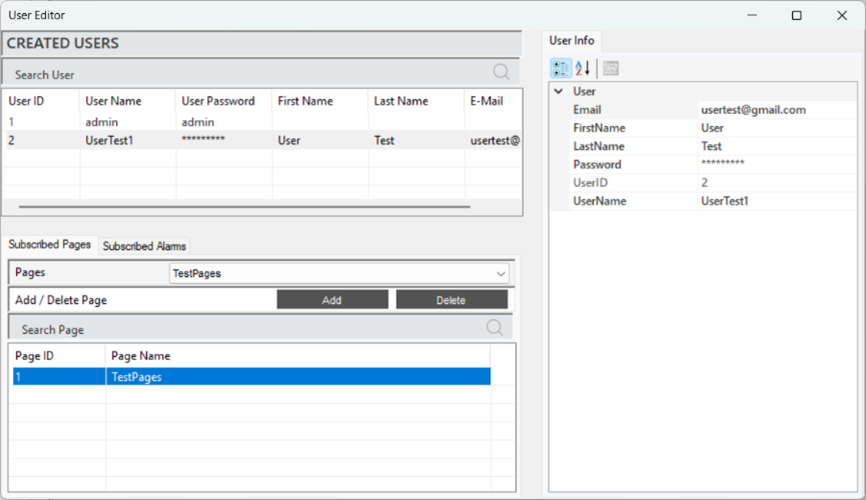
Figure 24 – Page Authorization
When a user is selected, the defined pages will appear in the "Subscribed Pages" section. To define a page, select the desired page in the "Pages" tab and click "Add" to complete the process. To delete a defined page, follow the same steps and click "Delete" at the end.
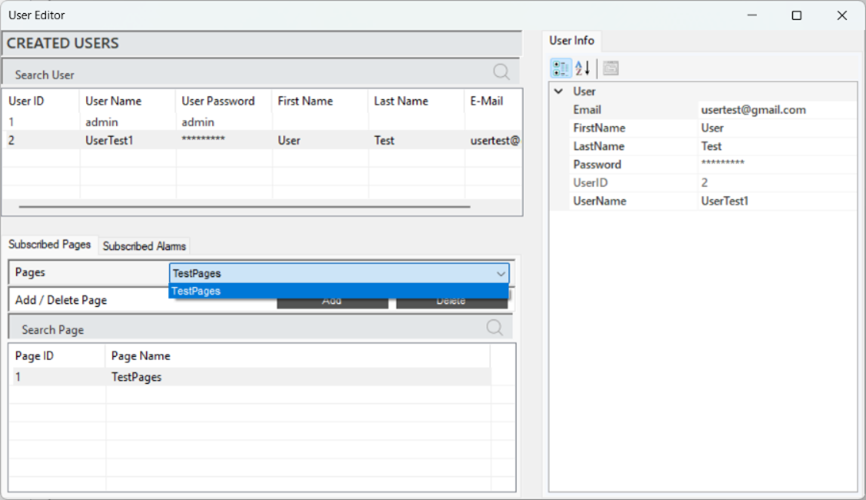
Figure 25 – Page Authorization
Alarm Authorization
Alarm authorization refers to the adjustments made to manage users' access rights to specific alarm notifications. This ensures that only authorized users can view and intervene in critical situations.
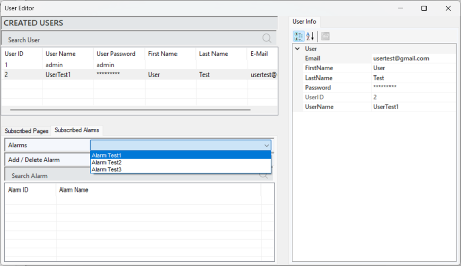
Figure 26 – Alarm Authorization
When a user is selected, the defined alarms will appear in the "Subscribed Alarms" section. To define an alarm, select the desired alarm in the "Alarms" tab and click "Add" to complete the process. To delete a defined alarm, follow the same steps and click "Delete" at the end.
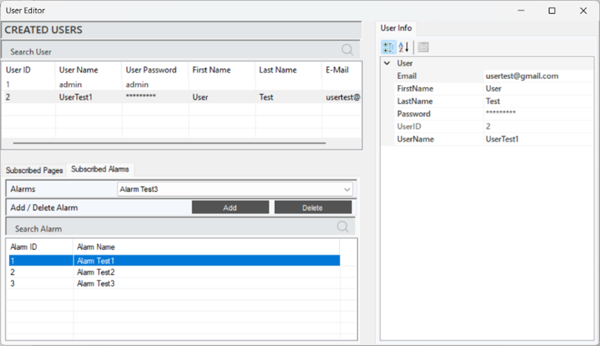
Figure 27 – Alarm Authorization
3.3 SMS EDITOR
It is a tool used to manage the sending of alarm and notification text messages (SMS) in the system. This editor allows users to define customized message content and specify the recipients, ensuring fast and effective communication about critical situations.
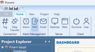
Figure 28 – SMS Editor
An SMS subscription is required to create SMS notifications.
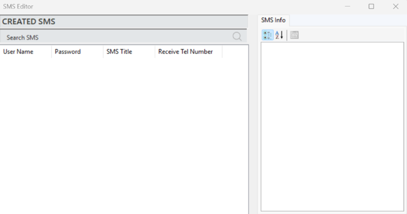
Figure 29 – SMS Information Popup
Creating a SMS Notification
After completing the subscription process, right-click on the "Created SMS" section in the editor and select "Add SMS" to create an SMS notification.
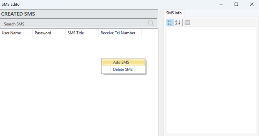
Figure 30 – Creating a SMS
In the opened window, fill in the subscription details along with the other parameters, and the SMS notification will be added.
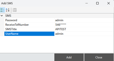
Figure 31 – Creating a SMS
The parameter descriptions are provided in the table below.
“Password” | Subscription password. |
“Receive TelNumber” | The phone number to which the SMS will be sent. |
“SMS Title” | The content of the SMS. |
“UserName” | Subscription username |
Table 4 – SMS Parameters
To edit an existing SMS notification, select the relevant notification and make changes from the "SMS Info" panel.
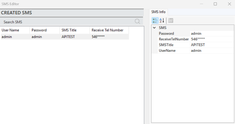
Figure 32 – SMS Info
SMS Notification Authorization
After the SMS notification is created, the alarm to which the notification will be linked must be defined. This process is carried out in the Alarm Editor. Once the relevant alarm is selected in the Alarm Editor, the alarm information will appear in the info panel. Here, the "SMS Active" parameter is changed to "True." This ensures that when the condition of the selected alarm is met, the user will receive a notification via SMS.
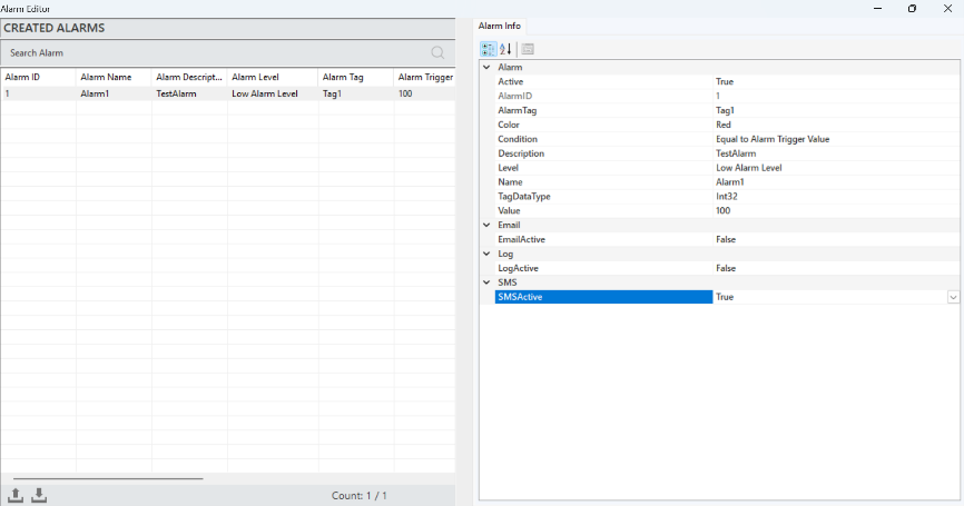
Figure 33 – SMS Defining
A sample SMS notification for testing purposes is shared in the image below.
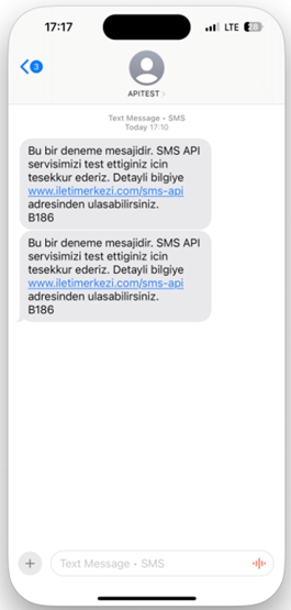
Figure 34 – SMS Message Example
3.4 E-MAIL EDITOR
It is a tool used to manage the sending of system alarms and notifications via email. This editor allows users to create customized message content and specify recipients, ensuring that critical information is communicated quickly and effectively.
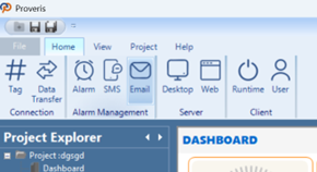
Figure 35 – E-Mail Editor
To create an email notification, the email settings must first be configured.
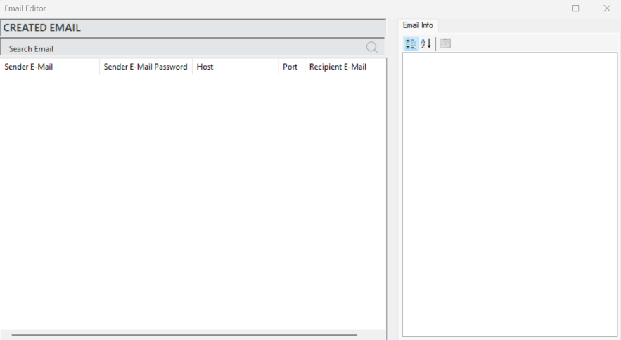
Figure 36 – E-Mail Information Popup
Creating an E-Mail Notification
After completing the membership process, right-click on the "Created E-MAIL" section in the editor and select "Add E-mail" to create an email notification.
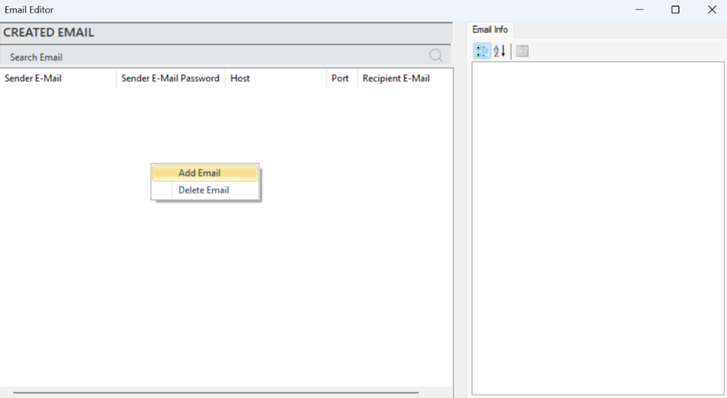
Figure 37 – Creating a E-Mail
In the opened window, fill in the membership details along with other parameters to add the notification. The parameter descriptions are provided in the table below.
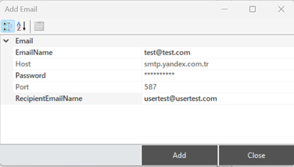
Figure 38 – Creating a E-Mail
The parameter descriptions are provided in the table below.
“E-mail Name” | Membership username information |
“Host” | Server address information |
“Password” | Membership password information |
“Port” | Server port information |
“Recipient E-mail Name” | Recipient's e-mail information |
Table 5 – E-Mail Parameters
To edit an existing E-mail notification, select the relevant notification and make changes in the "E-Mail Info" panel.
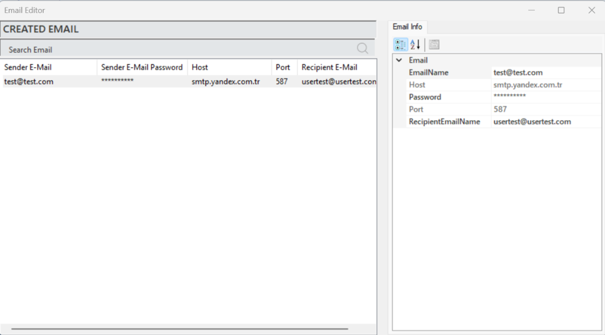
Figure 39 – E-Mail Info
E-mail Notification Authorization
After creating an e-mail notification, the alarm to which the notification will be linked must be defined. This process is performed in the Alarm Editor.
In the Alarm Editor, select the relevant alarm, and its information will appear in the information panel. Here, change the “E-mail Active” parameter to “True.” This way, when the condition of the alarm is met, a notification will be sent to the user via E-mail. The process steps are shown in the visual below.
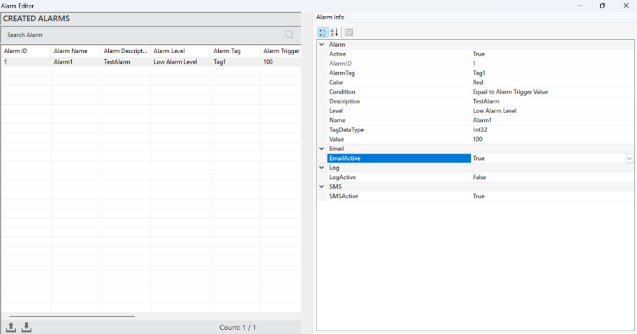
Figure 40 – E-Mail Notification Authorization
A sample of the email notification for testing purposes is shared in the visual below.
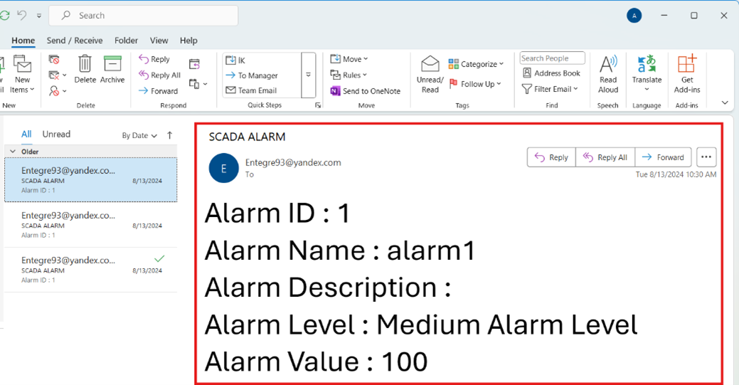
Figure 41 – E-Mail Notification Example
3.5 TAG EDITOR
This component allows for the addition and editing of channels, frames, and tags to the project. By creating, editing, and managing data tags, it enables systematic analysis and visualization. Through tags, data is easily categorized, and the analysis process is accelerated.
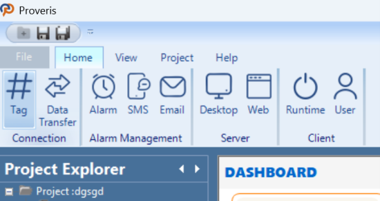
Figure 42 – Tag Editor
In the Tag Editor, the following operations can be performed:
Creating, editing and deleting channels
Creating, editing and deleting frames
Creating, editing and deleting tags
After a Tag is added, it is mandatory to specify which machine it belongs to. This is done by entering the MachineName in the Description field under the Tag Info section.
If Automatic mode is selected from the Setting page, two tags must be created for each machine:
One for general system operation,
And one for detecting whether the produced parts are correct.
In the system tag, only the machine name should be entered in the Description field.
In the tag used for correct product detection, the Description field must follow the format: "MachineName:Output"
Here, :Output is a fixed suffix and must always be included. Only the machine name can vary.
This configuration is essential for the system to correctly associate sensor data with the corresponding machine.
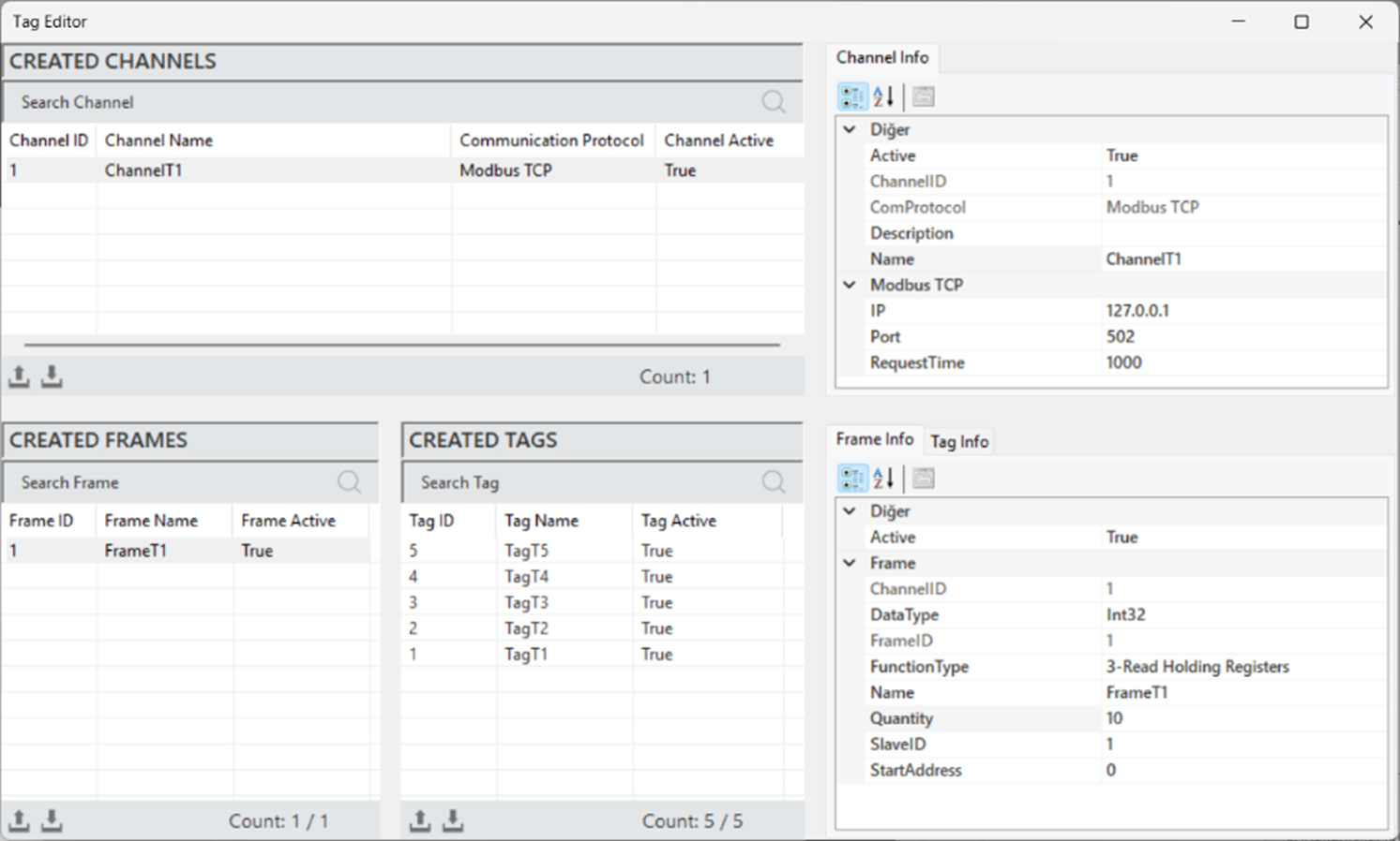
Figure 43 – Tag Editor
3.6 ALARM EDITOR
The Alarm Editor manages all alarms, allowing the creation and editing of alarms under specific conditions. In OEE systems, it detects critical events, provides immediate feedback to operators, and informs them about potential risks.
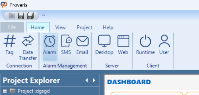
Figure 44 – Alarm Editor
The appearance of the Alarm Editor is shown in the image below.
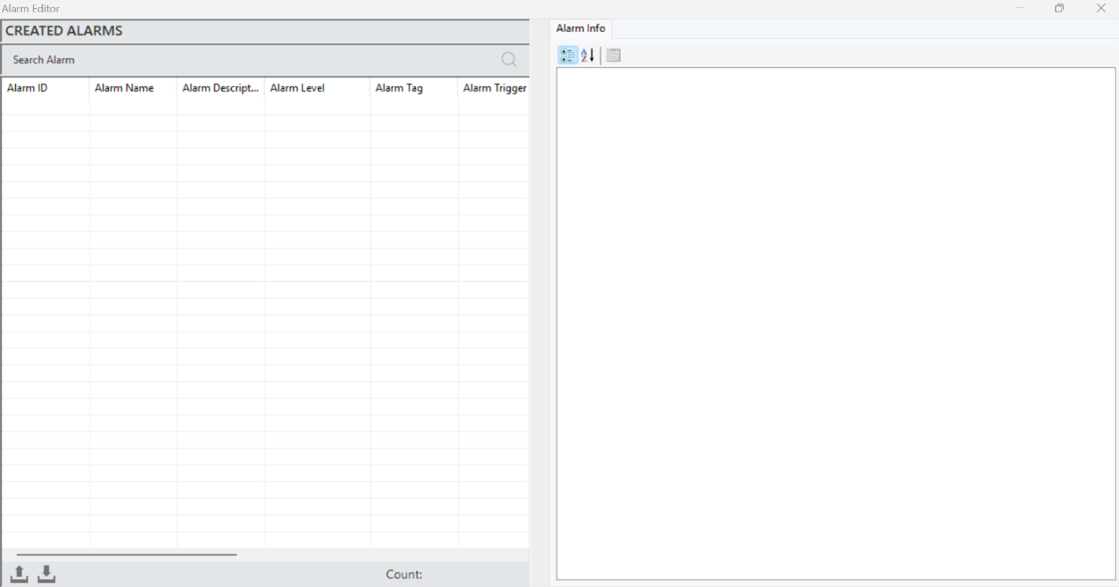
Figure 45 – Alarm Editor
3.6.1 Alarm Creation
To create an alarm, right-click in the "Created Alarms" area of the editor and select "Add Alarm." After entering the information for the alarm in the opened window, click "Add" to create the alarm.
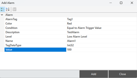
Figure 46 – Creating a Alarm
Alarm Structure
To access and make adjustments to alarm information, when an alarm is selected, all the details are reflected in the "Alarm Information" panel.
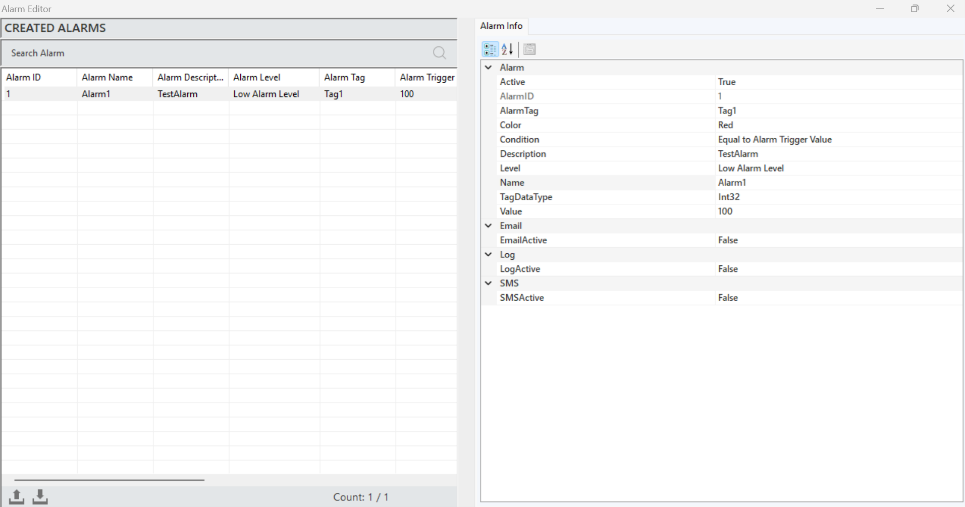
Figure 47 – Alarm Info
The parameter descriptions are presented in the table below.
“Alarm Tag” | Specifies the source tag that will trigger the alarm. |
“Color” | A parameter that provides the visual representation of the alarm. |
“Condition” | Defines the conditions required to trigger the alarm. |
“Description” | Specifies the description text for the alarm. |
“Level” | Determines whether the alarm is classified as high, medium, or low. |
“Name” | A clear and descriptive name for the alarm |
“TagDataType” | Used to specify the type of data being monitored or controlled. |
“Value” | The threshold value set to trigger the alarm. |
“E-mail Active” | Controls email notifications for the alarm. |
“Log Active” | Determines whether the alarm states are logged into the database. |
“SMS Active” | Controls SMS notifications for the alarm. |
Table 6 – Alarm Info
3.6.2 Alarm Windows
There are two alarm panels available in the editor for monitoring and managing alarms: one for the server and one for the client.
Server Alarm Panel
Represents the central management point of the system and allows the monitoring of all active alarms. The alarm statuses are provided to the user in real-time. Additionally, it stores historical alarm data, contributing to analysis and reporting processes.
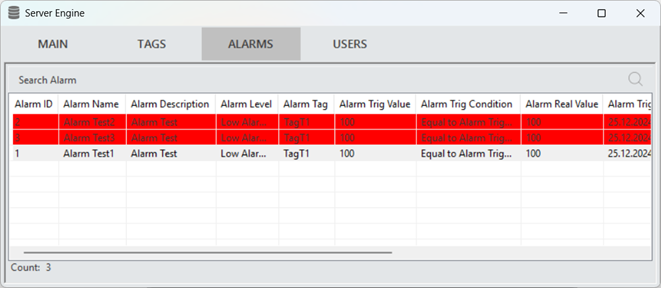
Figure 48 – Server Alarm Panel
Client Alarm Panel
When alarms created in the Editor interface are triggered on the Client Screen, they appear in the Alarms section.
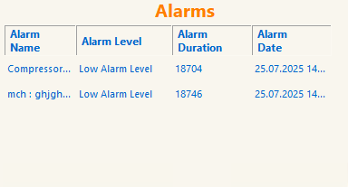
Figure 49 – Client Alarm Panel
3.7 DATA TRANSFER EDITOR
In the editor, the data transfer command is used to define the source and target tags. During the desired data update interval, it transfers the data read from the source tag to the target tag.
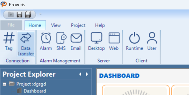
Figure 50 – Data Transfer Editor
Data Transfer Creation
To create a data transfer, right-click within the "Created Data Transfers" area in the editor and select "Add Data Transfer." After entering the required tag information in the opened window, click "Add" to create the data transfer.
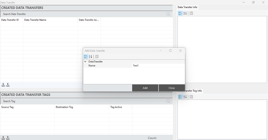
Figure 51 – Creating a Data Transfer
To access and edit the Data Transfer details, select a transfer and make the changes in the "Data Transfer Information" panel.
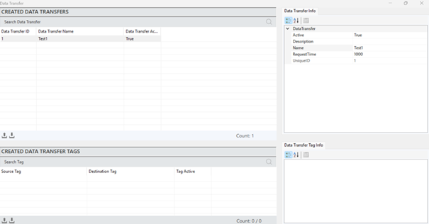
Figure 52 – Data Transfer Editor
The parameter descriptions are provided in the table below.
“Active” | Determines whether the data transfer is active or inactive. |
“Description” | Defines the description of the data transfer. |
“Name” | Defines the name of the data transfer. |
“Request Time” | Specifies the frequency of data updates for the tags. |
“Recipe ID” | A unique identification number assigned to each recipe. |
Table 7 – Data Transfer Parameters
Defining Data Transfer Tags
To define a tag, a data transfer command must first be created. After selecting the created command, right-click in the "Created Data Transfers" section and click "Add Tag."
In the window that opens, enter the required tag details and click "Add" to create the tag.
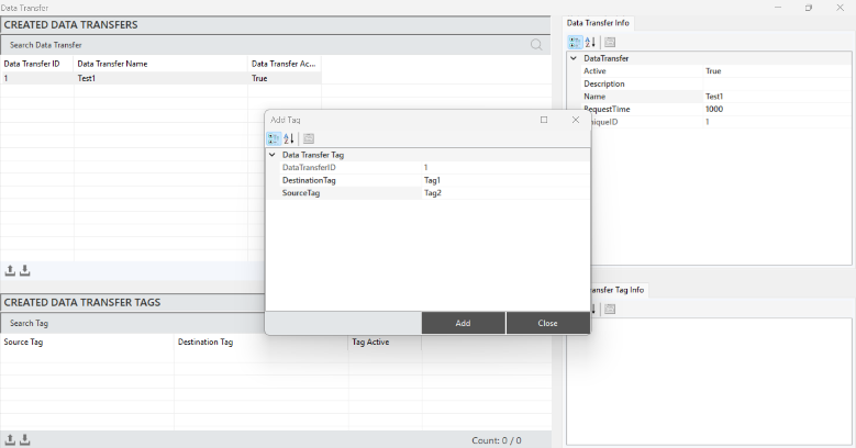
Figure 53 – Defining Data Transfer Tag
To access and make changes to the data transfer tag information, select a data transfer, and all the details will be displayed in the "Data Transfer Tag Information" panel.
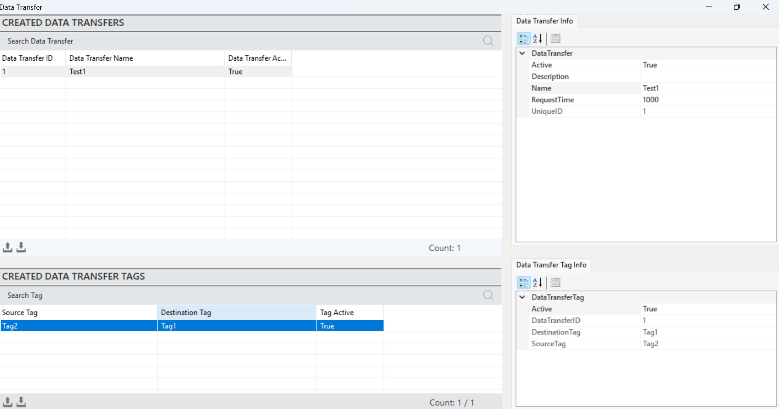
Figure 54 – Data Transfer Tag Info
· The parameter descriptions are provided in the table below.
“Active” | A parameter that indicates whether the data transfer is currently active. |
“Data Transfer ID” | A unique identification number assigned to each data transfer operation. |
“Destination Tag” | The target location where the data will be transferred. |
“Source Tag” | The source location from which the data will be transferred. |
Table 8 – Data Transfer Tag Parameters
3.8 OPTIONS
This section defines the specifications of the camera to be used in the AR (Augmented Reality) system. It includes the selection criteria for the camera and the input of its physical dimensions. The correct choice of camera is critical for ensuring optimal image quality and accurate spatial alignment in AR applications.
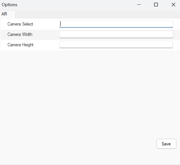
Figure 55 – Options