System Interface
3. SYSTEM INTERFACE
The Omnivex SCADA system interface is designed to efficiently manage industrial automation processes, offering a user-friendly and accessible layout. Featuring a modern design, it includes various visual and functional elements to enhance user interaction and streamline business process management. The interface is highly configurable to improve functionality and user experience, minimizing potential challenges.
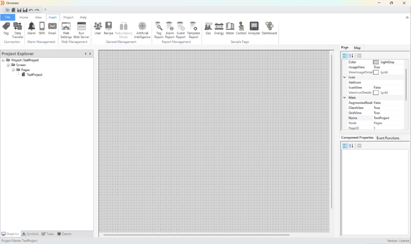
Figure 1 – System Interface
The main menu serves as the central control hub, providing quick access to essential modules, including project operations, tool management, and editor settings. Users can customize dynamic components for faster task completion, thereby optimizing workflow and improving overall system management.
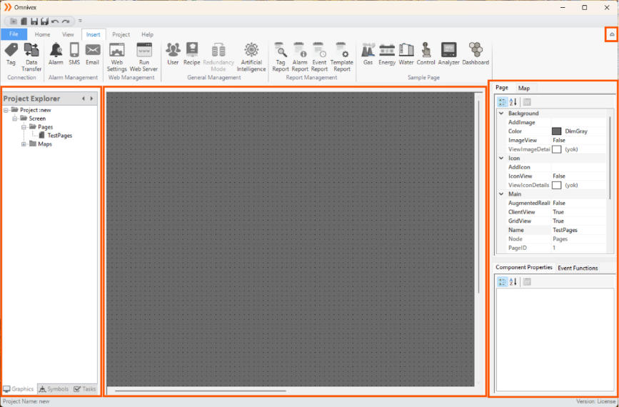
Figure 2 – Interface Controls
Detailed explanations of the interface controls are provided in the following sections.
3.1 Toolbar
The toolbar is an essential tool that provides quick access to the program's core functions. It includes main categories such as "File", "Home", "View,", “Insert”, “Project” and "Help" offering options for file creation, saving, project tools, views, and support.
Effective use of the menu bar contributes to the program's efficient operation and enhances the user experience. The options in the Omnivex SCADA interface menu bar are listed below:
| File | Home | View | Insert | Project | Help |
|---|---|---|---|---|---|
Table 1 – Toolbar
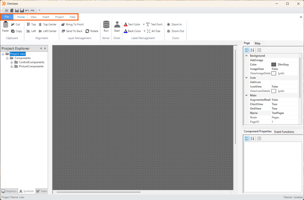
Figure 3 – Menu Bar
All the options in the menu bar are explained in detail in the following sections.
3.1.1 File
In Omnivex SCADA, the "File" tab in the interface is used for project edits and file operations.
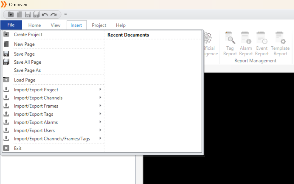
Figure 4 - File
| File | Description |
|---|---|
| Create project | Creates a new project. |
| New page | Adds a new page within the created project. |
| Save page | Saves the current page in the project. |
| Save All Page | Saves all pages in the project. |
| Save page as | Saves the page(s) in the project with a different extension. |
| Load page | Loads the project pages. |
| Import/Export project | Command for importing and exporting the project file. |
| Import/Export channels | Command for importing and exporting channel data. |
| Import/Export frames | Command for importing and exporting frame data. |
| Import/Export tags | Command for importing and exporting tag data. |
| Import/Export alarms | Command for importing and exporting alarm data. |
| Import/Export users | Command for importing and exporting user information. |
| Import/Export channels/frames/tags | Command for importing and exporting channel, frame, and tag data |
| Exit | Exits the application. |
Table 2 – File Commands
*Note: (The files to be added must be in .xlsx format.)
3.1.2 Home
The project design provides a comprehensive toolbar for text editing and component configuration. This toolbar enables users to make detailed adjustments to graphic and text elements, optimize data visualizations, and create interactive presentations.
Additionally, page zoom functions allow users to examine the components on the design page more effectively.
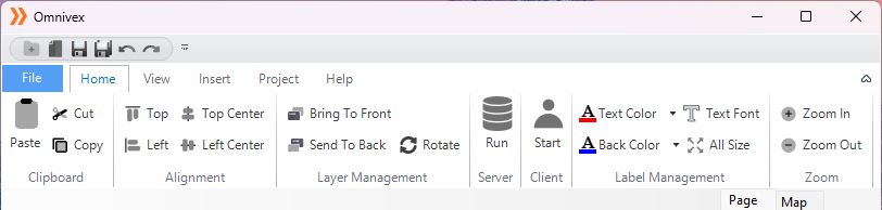
Figure 5 - Toolbar
Clipboard
The Clipboard is a virtual space used to temporarily store text, images, or other data on your computer. This allows you to copy any information from one place and paste it elsewhere. In the Omnivex SCADA system, this feature allows you to easily perform tasks such as moving or deleting components.
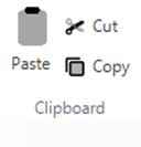
Figure 6 - Clipboard
Cut: Removes the selected component from its original location and stores it in the clipboard. When pasted, it is completely removed from the original location.
Copy: Stores the selected component in the clipboard but leaves it in its original location. When pasted, both the copied component in the clipboard and the original component remain in place.
Paste: Pastes the last copied or cut component from the clipboard to the position of the cursor.
Alignment
Alignment is the process of positioning elements in a design to ensure an organized and visually appealing layout. It involves adjusting objects relative to each other or to specific edges (top, left, center) to maintain consistency, balance, and readability.
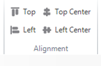
Figure 7 - Alignment
Align Top: Aligns selected elements to the top edge, ensuring consistency and a clean layout.
Align Left: Aligns selected elements to the left edge, contributing to a well-organized design.
Align to Top from Centers: Aligns the center points of selected elements to the top edge for even distribution and balance.
Align to Left from Centers: Aligns the center points of selected elements to the left edge, creating a symmetrical and balanced layout.
Layer Management
Layer Management involves organizing and controlling the stacking order of elements in a design or interface. It allows users to arrange elements in layers, ensuring certain objects appear in front or behind others. This is crucial for maintaining clarity and structure, particularly in complex or overlapping designs.
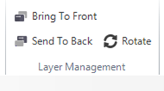
Figure 8 - Layers Management
Bring to Front: Moves the selected element to the topmost layer, making it appear in front of all other elements. This is useful for highlighting important items or overlays.
Send to Back: Moves the selected element to the bottommost layer, positioning it behind all other elements. This is helpful for placing background elements without deleting them.
Rotate: Rotates the selected element 90 degrees clockwise around its center or a defined pivot point. This is commonly used to adjust the orientation for better alignment or to fit the element within a layout.
Server
The "Server" function starts the server component of the SCADA system. It initializes and activates the server, which manages communication, data processing, and connected devices. The server acts as the central hub, collecting and transmitting real-time data from devices and sensors to other system components, such as client applications. It is essential for establishing and maintaining the SCADA system's communication infrastructure.
Figure 9 - Server
Client
The "Client" function starts the client component of the SCADA system. It launches the client interface, connects to the server, and allows users to view real-time data, interact with the system, and control devices. The client serves as the user interface, enabling data visualization, monitoring, and control, while communicating with the server to retrieve and display processed data.
Figure 10 - Client
Label Management
Label Management allows users to customize the appearance of text labels, ensuring clarity and alignment with the overall design.
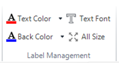
Figure 11 - Label Management
Text Font: Customize the font type, size, and thickness of text labels for better readability and visual appeal.
Text Color: Change the color of text labels to match the design theme or enhance visibility, using a color palette or custom code.
Back Color: Set a background color for text labels to improve contrast and make them stand out, especially for emphasizing key information.
All Size: Adjust the size of both text and graphical components, ensuring proper scaling and alignment across the interface.
Zoom
Zoom tools allow users to examine the display in more detail. These tools enable users to increase or decrease the size of graphic and text elements, making data analysis more efficient.
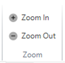
Figure 12 - Zoom
Page Zoom (+): This function allows zooming in on the view. It is used to help users focus on details and make complex graphics clearer.
Page Zoom Out (-): This function allows zooming out on the view. This feature enables users to see a larger area and obtain an overall view.
3.1.3 View
Adjustments can be made in the windows located on the left side of the interface. You can hide or show the windows depending on the project. The view settings are managed from here
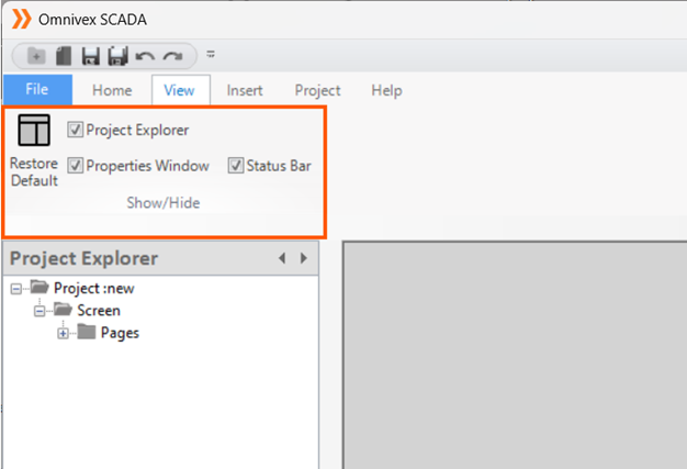
Figure 13 - View
Project Explorer
The Project Explorer is a panel in Omnivex SCADA that displays and manages the entire project structure, providing quick access to SCADA components. It organizes components hierarchically for efficient management and enables users to quickly find specific elements.
Graphics: Enables the editing and viewing of project pages.
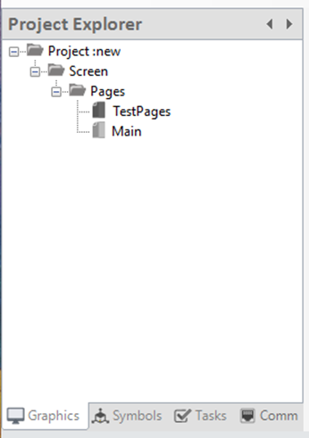
Figure 14 - Graphics
Symbols: Users can add, edit, or delete project components.
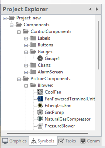
Figure 15 - Symbols
Tasks: Provides access to alarms, recipes, data transfers, and reports, with options for editing.
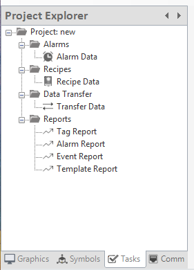
Figure 16 - Tasks
Communication: Allows access to all details related to channels, frames, tags, and other communication elements.
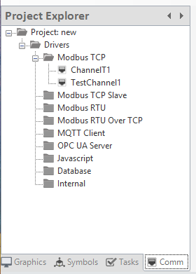
Figure 17 - Communication
Workspace Area
The Workspace Area is the main space in the Omnivex SCADA interface where users design and modify their projects. It allows for the placement and customization of graphical components and offers features such as dynamic visualization, layered structure, and multi-component management. Additionally, the zoom-in/out function enables detailed adjustments and an overall view of the project.

Figure 18 - Working Area
Properties Window
Properties Window is a panel in the Omnivex SCADA interface that allows users to view and edit the properties of selected components. Through this window, users can easily modify attributes such as color, size, and position of graphical elements. Additionally, component labeling and function assignments can be done here. The Properties Window is where all page settings are configured, including page layout, background colors, and other related adjustments. Users can also modify the behaviors and functions of components, ensuring the project is fully customized and optimized.
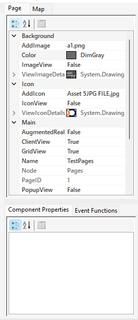
Figure 19 - Properties Window
Status Bar
The Status Bar is located at the bottom of the Omnivex SCADA interface and displays the project name and license status.
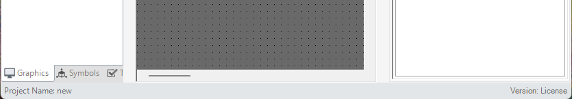
Figure 20 - Status Bar
3.1.4 Insert
The "Insert" tab allows users to add and configure various system components and settings. This tab includes options for establishing connections, managing alarms, setting up web functionalities, handling general system management tasks, generating reports, and utilizing sample projects.
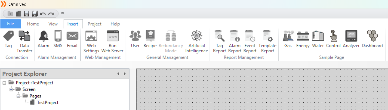
Figure 21 - Insert Tab
Connection
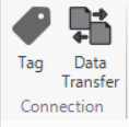
Figure 22 - Connection
Tag Editor: The "Tag Editor" is used to define and configure tags, which represent data points within the system. Users can edit tag properties and set parameters to align with system requirements.
Data Transfer Editor: The "Data Transfer Editor" facilitates the configuration of data transfer settings between systems or components. Users can define data protocols and ensure smooth communication.
Alarm Management
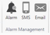
Figure 23 - Alarm Management
Alarm Editor: The "Alarm Editor" is used to define and customize alarm settings, including the conditions that trigger alarms and the actions that follow.
SMS Editor: The "SMS Editor" allows users to configure SMS notifications for alarm events. Users can define SMS templates and specify recipient details for alerting purposes.
Email Editor: The "Email Editor" enables users to set up email notifications for alarms or events. It allows customization of email templates and the configuration of recipient information.
Web Management
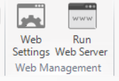
Figure 24 - Web Management
Web Settings: "Web Settings" allows users to configure the parameters for web interfaces, ensuring smooth integration with web-based components and remote access functionalities.
Run Web Server: The "Run Web Server" option starts the web server, enabling access to the system’s web interface for remote monitoring and control.
General Management
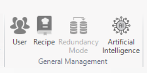
Figure 25 - General Management
User Editor: The "User Editor" allows the creation and management of user accounts and access rights. Users can define roles, permissions, and security settings for system access.
Recipe Editor: The "Recipe Editor" is used to create and manage predefined system configurations, such as process settings or production recipes, for efficient operations.
Redundancy Mode: The "Redundancy Mode" option enables high availability by configuring redundancy settings, ensuring system reliability in case of hardware or software failures.
Artificial Intelligence: The "Artificial Intelligence" section integrates AI features into the system for enhanced decision-making, predictive analytics, and optimization.
Report Management
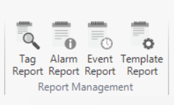
Figure 26 - Report Management
Tag Report: The "Tag Report" generates detailed reports based on tag data, helping users analyze and visualize system performance.
Alarm Report: The "Alarm Report" summarizes alarm events and provides insights into alarm occurrences, durations, and responses.
Event Report: The "Event Report" offers detailed information on specific system events, including timestamps and related activities.
Template Report: The "Template Report" allows users to generate reports based on pre-defined templates, ensuring consistency and ease of reporting.
Sample Project
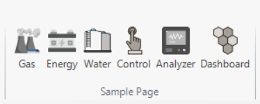
Figure 27 - Sample Project
Gas: The "Gas" sample project demonstrates configurations for gas-related systems, offering a reference for monitoring and control.
Energy: The "Energy" sample project provides templates for energy management, helping users implement energy-related systems efficiently.
Water: The "Water" sample project offers configurations for water treatment and management systems, providing a solid foundation for water-related projects.
Control: The "Control" sample project demonstrates control system configurations, suitable for users looking to implement control-related systems.
Analyzer: The "Analyzer" sample project provides a reference for integrating analyzer components into SCADA systems, showcasing data analysis capabilities.
Dashboard: The "Dashboard" sample project offers pre-configured dashboard templates for displaying system data in a visual format, ideal for monitoring and analysis.
3.1.5 Project
The "Project" tab provides essential tools for managing and configuring projects within the software. It includes options for importing, exporting, and editing project files, as well as adjusting client and system settings. This section is designed to streamline project workflows and enhance user efficiency.
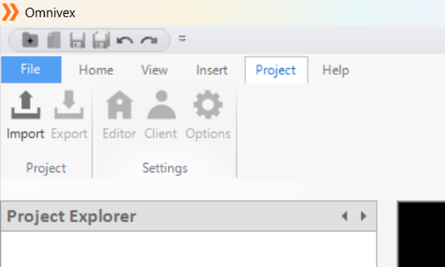
Figure 28 - Project
Import: The "Import" function allows users to bring external project files into the software. It supports various file formats, enabling the integration of pre-existing data and configurations into the current project.
Export: The "Export" option enables users to save project files in different formats for external use. This function facilitates sharing, backup, or transferring project data to other systems while maintaining compatibility.
Editor: The "Editor" provides users with the tools needed to modify and configure project components. Through the editor settings, users can customize project elements, adjust layouts, and implement specific changes to suit operational requirements.
Client: The "Client" settings allow for configuration of client-side parameters and connections. Users can manage client devices, adjust connection settings, and optimize interactions between the client and the system.
Options: The "Options" menu offers access to general system settings and preferences. It provides users with the flexibility to configure system behaviors and prepare for future feature updates or customizations.
3.1.6 Help
The "Help" tab provides users with access to various support resources and documentation. It includes options for getting assistance, reviewing examples, accessing product-related information, and understanding licensing terms.
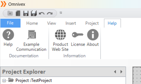
Figure 29 - Help
Help: The "Help" option directs users to the software's built-in support and documentation. It provides detailed guidance on using features, troubleshooting issues, and accessing additional resources to enhance the user experience.
Example Communication: The "Example Communication" section offers predefined communication templates and examples. These templates help users understand common communication protocols and ensure correct implementation within the system.
Product Website: The "Product Website" link takes users to the official product website. Here, they can find more information about features, updates, system requirements, and other resources to better understand and utilize the software.
License: The "License" option displays the terms and conditions of the software license. Users can review the legal agreements, including usage rights, restrictions, and other important legal information regarding the software.
About: The "About" section provides detailed information about the software version, copyright details, and the development team. It also includes contact information for support and feedback.
3.2 User Editor
The user editor is used to manage the roles and access rights of users in the system. It allows adding new users, editing existing users, or deleting users.
The editor manages page and alarm authorizations, ensuring that users can only access the information necessary for their tasks. Monitoring user activities enhances system security.
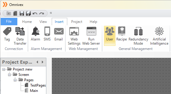
Figure 30 – User Editor
Creating a User Account
In the editor window, the "Created Users" section contains the registered user information. User addition and deletion operations are performed in this area. The general appearance of the editor is shown in the image below.
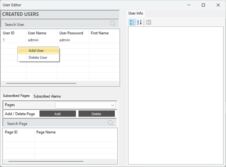
Figure 31 – Creating a User
To create a new user, right-click and select the option to add a user. Enter the username, password, and email information to add the user.
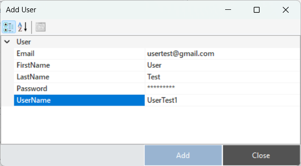
Figure 32 – Creating a User
Editing a User Account
To access and edit user information, the relevant user is selected. All details about the user are displayed in the "User Info" section of the panel. Updates can be made to all information, such as password and email, as needed.
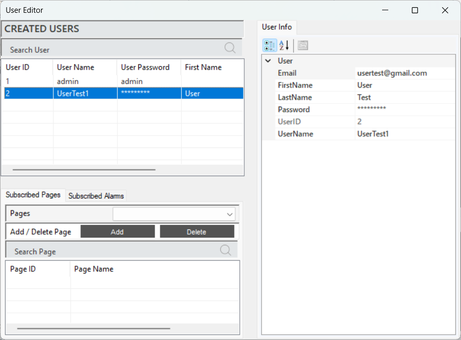
Figure 33 – User Info
The descriptions of the parameters related to the user account are provided in the table below.
| “Email” | User's email contact information |
|---|---|
| “First Name” | User's first name |
| “Last Name” | User's last name |
| “Password” | Password information to protect the user's account |
| “User ID” | A unique identification number assigned to each user in the system |
| “User Name” | User's login name in the system |
Table 3 – User Info
Page Authorization
Page authorization refers to the adjustments made to manage users' access rights to specific pages. This process ensures that only authorized users can access the necessary information, aiming to maintain system security.
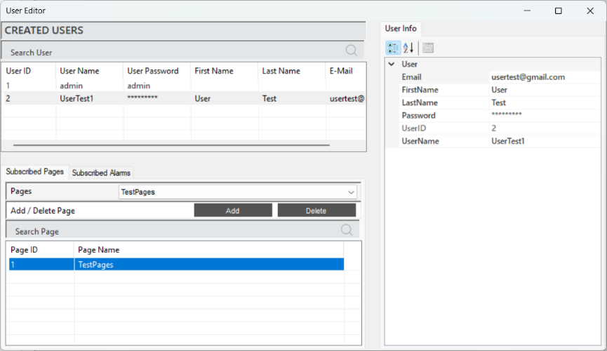
Figure 34 – Page Authorization
When a user is selected, the defined pages will appear in the "Subscribed Pages" section. To define a page, select the desired page in the "Pages" tab and click "Add" to complete the process. To delete a defined page, follow the same steps and click "Delete" at the end.
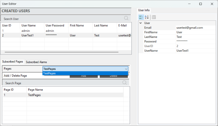
Figure 35 – Page Authorization
Alarm Authorization
Alarm authorization refers to the adjustments made to manage users' access rights to specific alarm notifications. This ensures that only authorized users can view and intervene in critical situations.
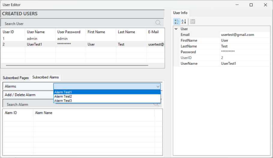
Figure 36 - Alarm Authorization
When a user is selected, the defined alarms will appear in the "Subscribed Alarms" section. To define an alarm, select the desired alarm in the "Alarms" tab and click "Add" to complete the process. To delete a defined alarm, follow the same steps and click "Delete" at the end.
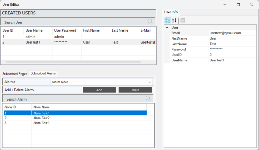
Figure 37 - Alarm Authorization
3.3 SMS Editor
It is a tool used to manage the sending of alarm and notification text messages (SMS) in the system. This editor allows users to define customized message content and specify the recipients, ensuring fast and effective communication about critical situations.
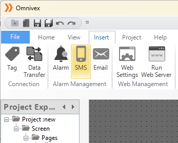
Figure 38 - SMS Editor
Creating a SMS Notification
After completing the subscription process, right-click on the "Created SMS" section in the editor and select "Add SMS" to create an SMS notification.
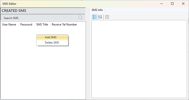
Figure 39 - SMS Notification
In the opened window, fill in the subscription details along with the other parameters, and the SMS notification will be added.
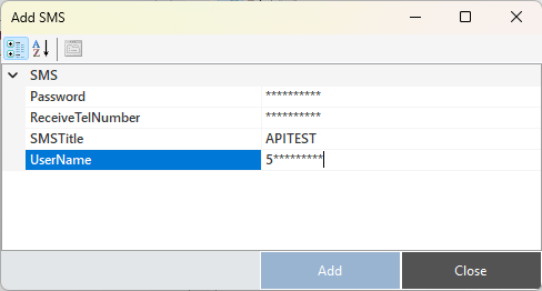
Figure 40 – SMS Notification
The parameter descriptions are provided in the table below.
| “Password” | Subscription password. |
|---|---|
| “Receive TelNumber” | The phone number to which the SMS will be sent. |
| “SMS Title” | The content of the SMS. |
| “UserName” | Subscription username |
Table 4 - SMS Parameters
To edit an existing SMS notification, select the relevant notification and make changes from the "SMS Info" panel.
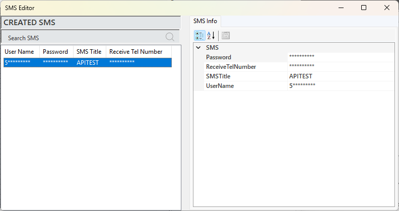
Figure 41 - SMS Notification
SMS Notification Authorization
After the SMS notification is created, the alarm to which the notification will be linked must be defined. This process is carried out in the Alarm Editor. Once the relevant alarm is selected in the Alarm Editor, the alarm information will appear in the info panel. Here, the "SMS Active" parameter is changed to "True." This ensures that when the condition of the selected alarm is met, the user will receive a notification via SMS.
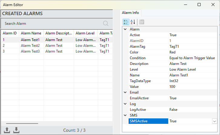
Figure 42 - SMS Defining
A sample SMS notification for testing purposes is shared in the image below.
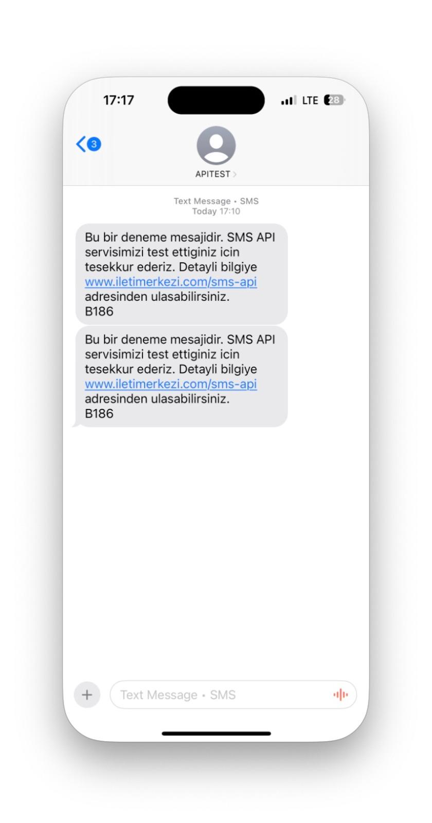
Figure 43 - SMS Notification
3.4 E-Mail Editor
It is a tool used to manage the sending of system alarms and notifications via email. This editor allows users to create customized message content and specify recipients, ensuring that critical information is communicated quickly and effectively.
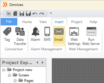
Figure 44 - E-Mail Editor
Creating an E-Mail Notification
After completing the membership process, right-click on the "Created E-MAIL" section in the editor and select "Add E-mail" to create an email notification.
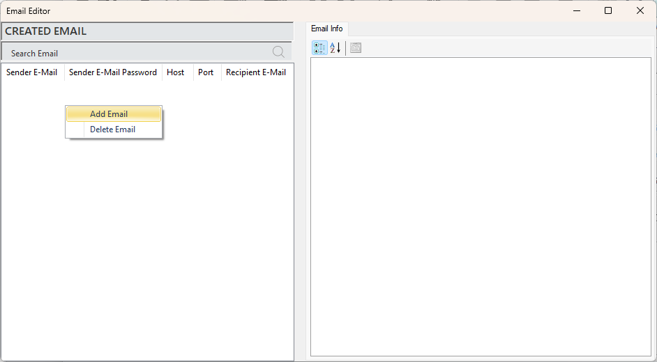
Figure 45 - E-Mail Notification
In the opened window, fill in the membership details along with other parameters to add the notification.
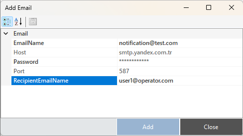
Figure 46 - E-Mail Parameters
The parameter descriptions are provided in the table below.
| “E-mail Name” | Membership username information |
|---|---|
| “Host” | Server address information |
| “Password” | Membership password information |
| “Port” | Server port information |
| “Recipient E-mail Name” | Recipient's e-mail information |
Table 5 - E-Mail Parameters
To edit an existing E-mail notification, select the relevant notification and make changes in the "E-Mail Info" panel.
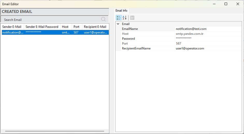
Figure 47 - E-Mail Info
E-mail Notification
After creating an e-mail notification, the alarm to which the notification will be linked must be defined. This process is performed in the Alarm Editor.
In the Alarm Editor, select the relevant alarm, and its information will appear in the information panel. Here, change the “E-mail Active” parameter to “True.” This way, when the condition of the alarm is met, a notification will be sent to the user via E-mail. The process steps are shown in the visual below.
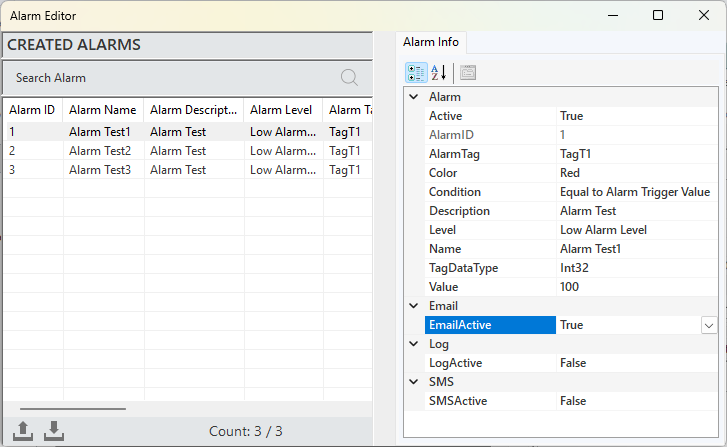
Figure 48 - E-Mail Notification
A sample of the email notification for testing purposes is shared in the visual below.
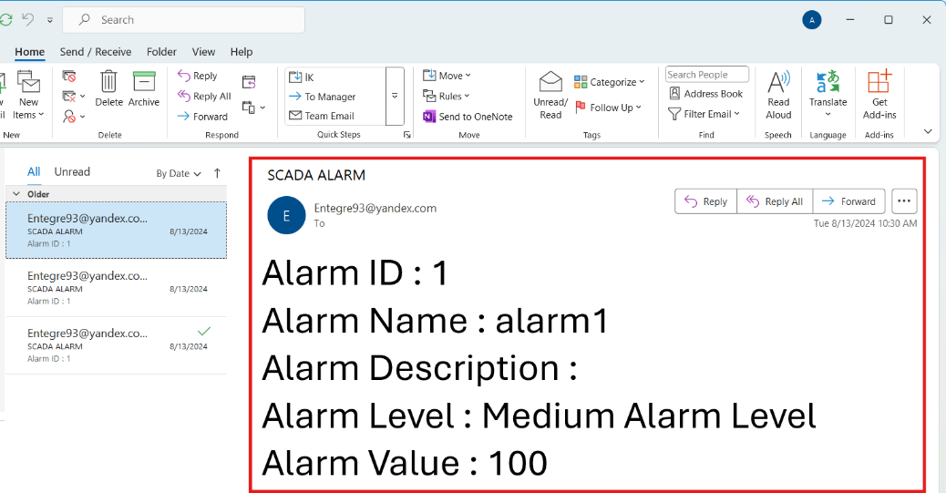
Figure 49 - E-Mail Notification
3.5 Tag Editor
This component allows for the addition and editing of channels, frames, and tags to the project. By creating, editing, and managing data tags, it enables systematic analysis and visualization. Through tags, data is easily categorized, and the analysis process is accelerated.
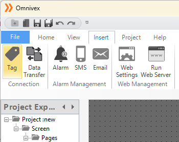
Figure 50 – Tag Editor
In the Tag Editor, the following operations can be performed:
Defining and editing channels
Defining and editing frames
Defining and editing tags
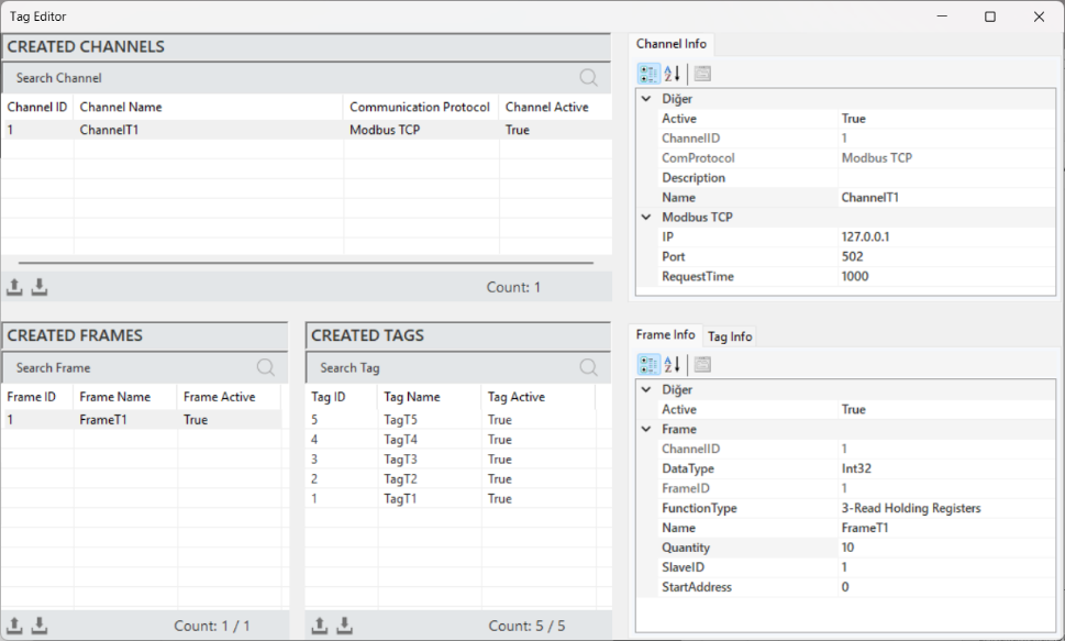
Figure 51 – Tag Editor
3.6 Alarm Editor
The Alarm Editor manages all alarms, allowing the creation and editing of alarms under specific conditions. In SCADA systems, it detects critical events, provides immediate feedback to operators, and informs them about potential risks.
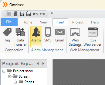
Figure 52 - Alarm Editor
The appearance of the Alarm Editor is shown in the image below.
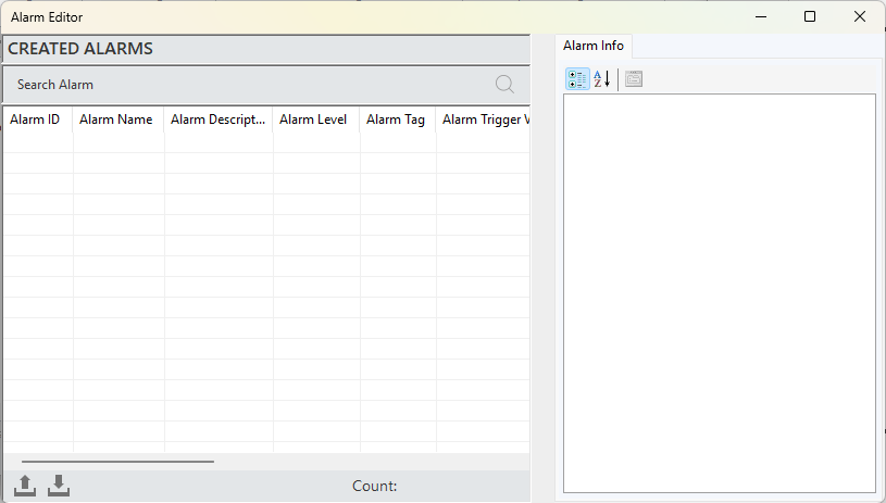
Figure 53 - Alarm Editor
3.6.1 Alarm Creation
To create an alarm, right-click in the "Created Alarms" area of the editor and select "Add Alarm." After entering the information for the alarm in the opened window, click "Add" to create the alarm.
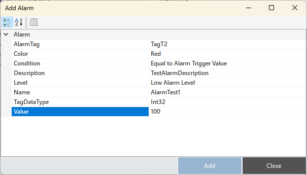
Figure 54 - Alarm Creation
Alarm Structure
To access and make adjustments to alarm information, when an alarm is selected, all the details are reflected in the "Alarm Information" panel.
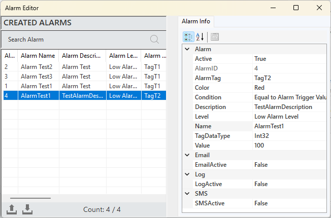
Figure 55 - Alarm Info
The parameter descriptions are presented in the table below.
| “Alarm Tag” | Specifies the source tag that will trigger the alarm. |
|---|---|
| “Color” | A parameter that provides the visual representation of the alarm. |
| “Condition” | Defines the conditions required to trigger the alarm. |
| “Description” | Specifies the description text for the alarm. |
| “Level” | Determines whether the alarm is classified as high, medium, or low. |
| “Name” | A clear and descriptive name for the alarm |
| “TagDataType” | Used to specify the type of data being monitored or controlled. |
| “Value” | The threshold value set to trigger the alarm. |
| “E-mail Active” | Controls email notifications for the alarm. |
| “Log Active” | Determines whether the alarm states are logged into the database. |
| “SMS Active” | Controls SMS notifications for the alarm. |
Table 6 - Alarm Info
3.6.2 Alarm Windows
There are two alarm panels available in the editor for monitoring and managing alarms: one for the server and one for the client.
Server Alarm Panel
Represents the central management point of the system and allows the monitoring of all active alarms. The alarm statuses are provided to the user in real-time. Additionally, it stores historical alarm data, contributing to analysis and reporting processes.
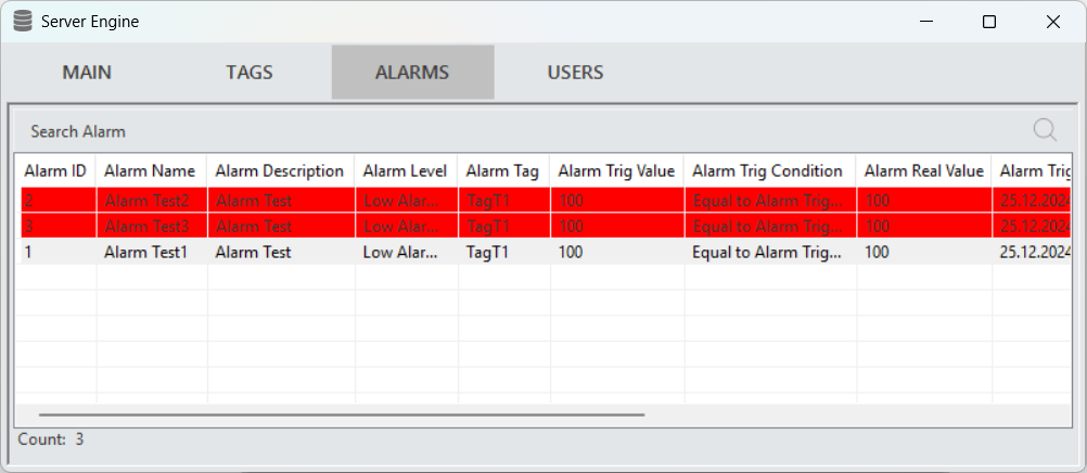
Figure 56 - Server Alarm Panel
Client Alarm Panel
It addresses the individual monitoring and management needs of users. Users can filter, view, and intervene with specific alarms when necessary.
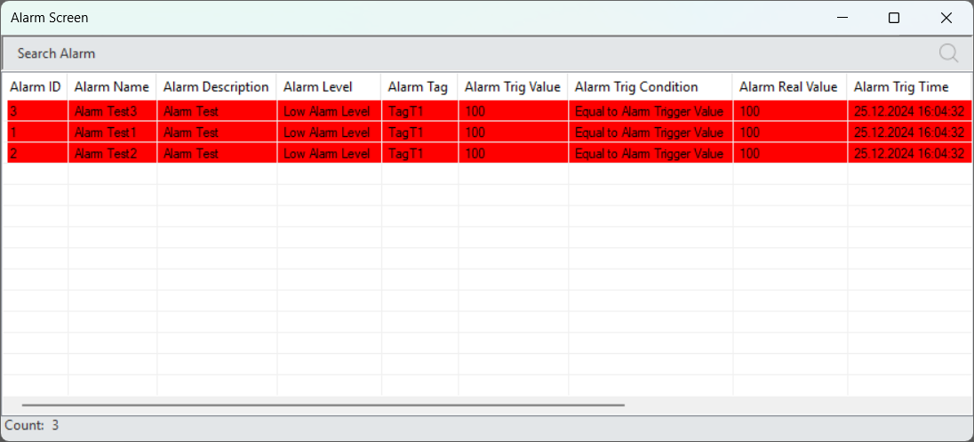
Figure 57 - Client Alarm Panel
Alarm Screen Components:
This component, which can be added to pages, allows users to visually monitor alarm statuses. Alarms that are triggered in real-time are displayed here.
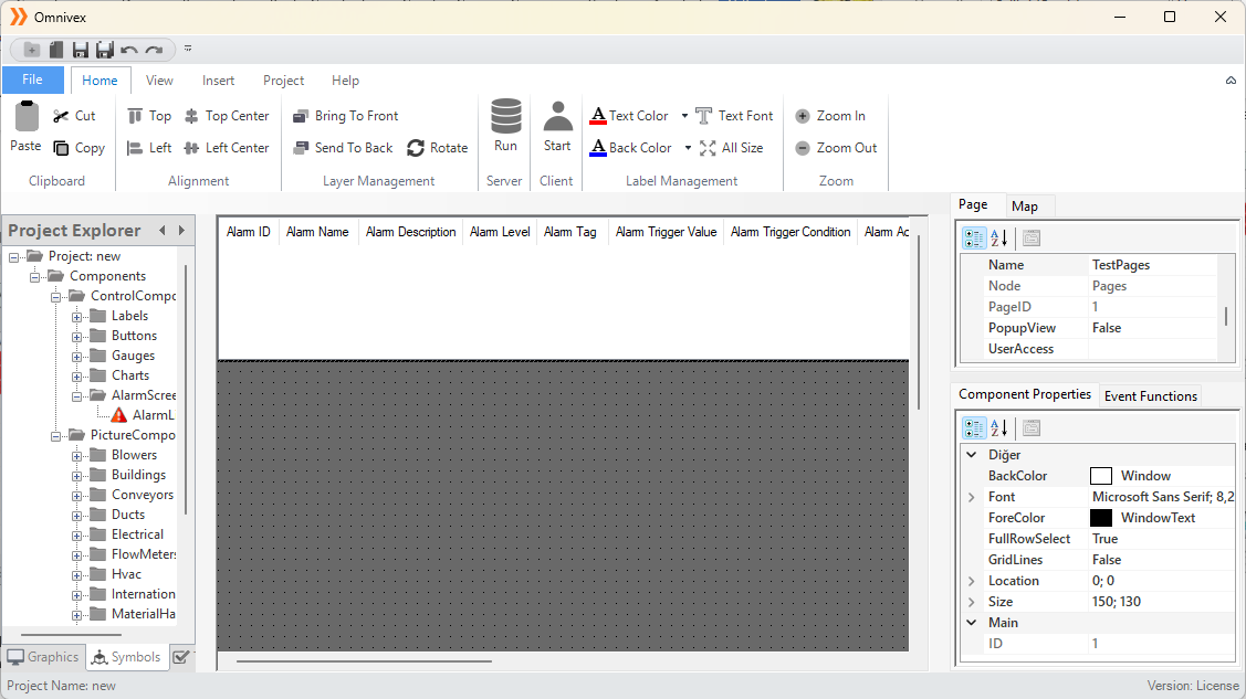
Figure 58 - Alarm Screen Components
3.7 Recipe Editor
It is a management tool that stores the parameters and settings required to perform a specific task. This system allows users to create a set of parameters for a particular task or production process and automatically apply these parameters.

Figure 59 – Recipe Editor
Recipe Creation
To create a recipe, right-click within the "Created Recipes" section in the editor and select "Add Recipe." In the window that opens, enter the required recipe details and click "Add" to create the recipe.
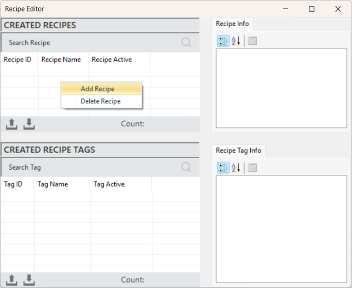
Figure 60 – Recipe Editor
Accessing and editing recipe details is done by selecting a recipe and making the changes in the "Recipe Information" panel.
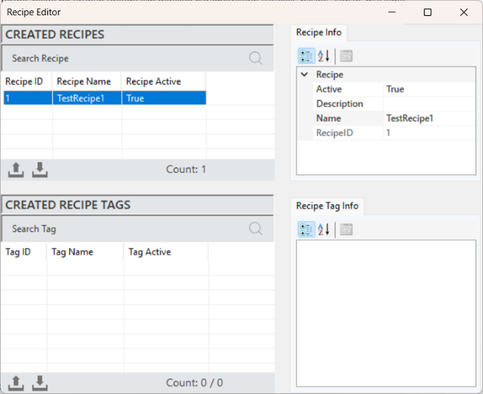
Figure 61 – Recipe Creation
The parameter details are as follows:
Active: A parameter that indicates whether the recipe is currently active.
Description: A text field providing detailed information about the recipe's content and purpose.
Name: A parameter representing the name of the recipe within the system.
Recipe ID: A unique identification number assigned to each recipe.
Recipe Tag Creation
To create a recipe tag, a recipe must first be created. Select a recipe and right-click in the "Created Recipe Tags" section to click on "Add Tag".
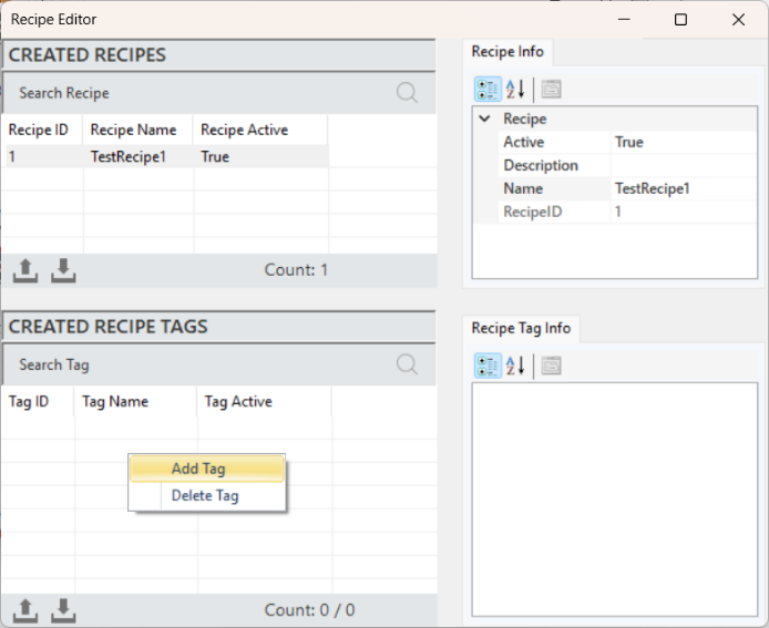
Figure 62 – Recipe Tag Creation
In the window that opens, enter the details for the tag and click "Add" to create the tag.
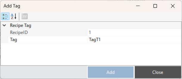
Figure 63 – Recipe Tag Creation
The values to be sent according to the recipe are entered into the created tags. This process is carried out by selecting the relevant tags and entering the values in the "Value" parameter within the "Recipe Tag Info" section.
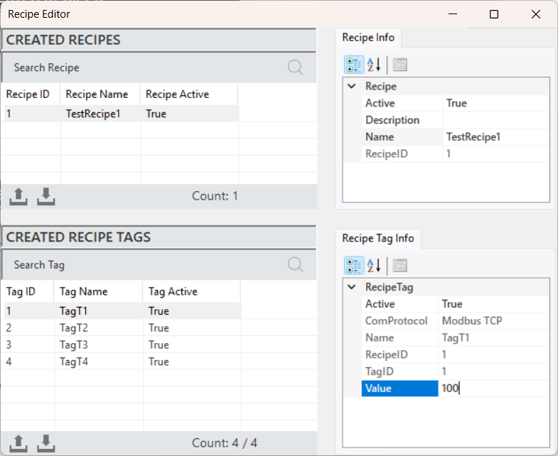
Figure 64 – Recipe Tag Creation
Once data assignments are made to all the tags within the recipe, the recipe is considered created. In the SCADA project, the recipe is then assigned to the relevant components, completing the process.
3.8 Data Transfer Editor
In the editor, the data transfer command is used to define the source and target tags. During the desired data update interval, it transfers the data read from the source tag to the target tag.
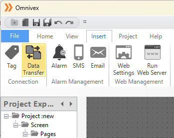
Figure 65 – Data Transfer Editor
Data Transfer Creation
To create a data transfer, right-click within the "Created Data Transfers" area in the editor and select "Add Data Transfer." After entering the required tag information in the opened window, click "Add" to create the data transfer.
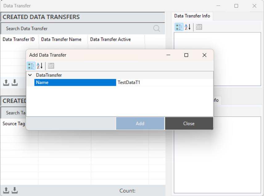
Figure 66 – Data Transfer Editor
To access and edit the Data Transfer details, select a transfer and make the changes in the "Data Transfer Information" panel.
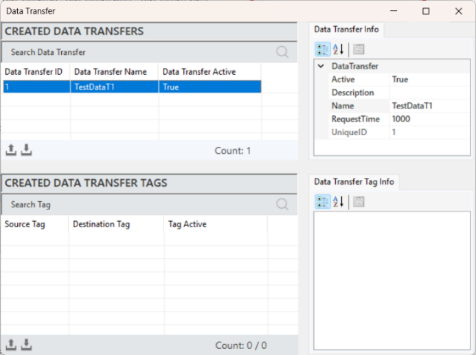
Figure 67 – Data Transfer Editor
The parameters details are as follows:
Active: Determines whether the data transfer is active or inactive.
Description: Defines the description of the data transfer.
Name: Defines the name of the data transfer.
Request Time: Specifies the frequency of data updates for the tags.
Recipe ID: A unique identification number assigned to each recipe.
Defining Data Transfer Tags
To define a tag, a data transfer command must first be created. After selecting the created command, right-click in the "Created Data Transfers" section and click "Add Tag."
In the window that opens, enter the required tag details and click "Add" to create the tag.
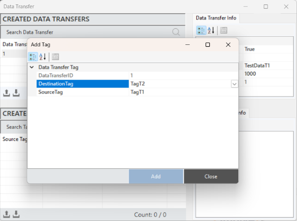
Figure 68 – Defining Data Transfer Tag
To access and make changes to the data transfer tag information, select a data transfer, and all the details will be displayed in the "Data Transfer Tag Information" panel.
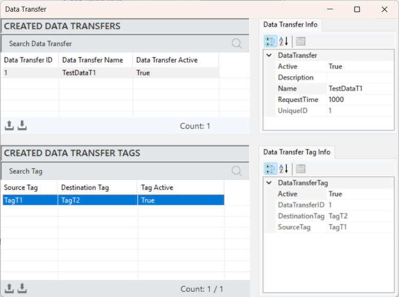
Figure 69 - Defining Data Transfer Tag
The parameter details are as follows:
Active: A parameter that indicates whether the data transfer is currently active.
Data Transfer ID: A unique identification number assigned to each data transfer operation.
Destination Tag: The target location where the data will be transferred.
Source Tag: The source location from which the data will be transferred.
3.9 Report Editor
The report editor provides a critical function for data analysis and performance evaluation. Users can create, store, and generate reports from historical data. This component allows for the collection, analysis, and preparation of comprehensive reports based on the data.
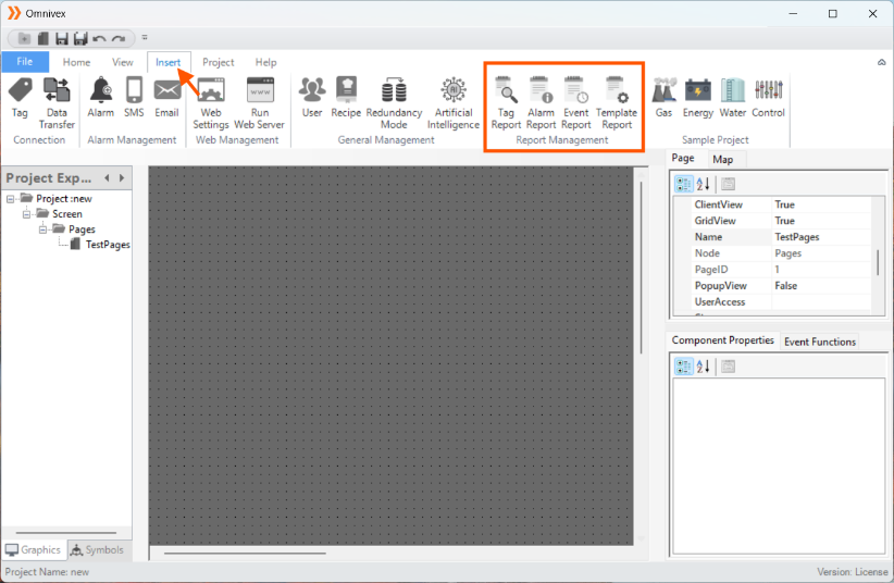
Figure 70 – Report Editor
The appearance of the data transfer editor is as follows:
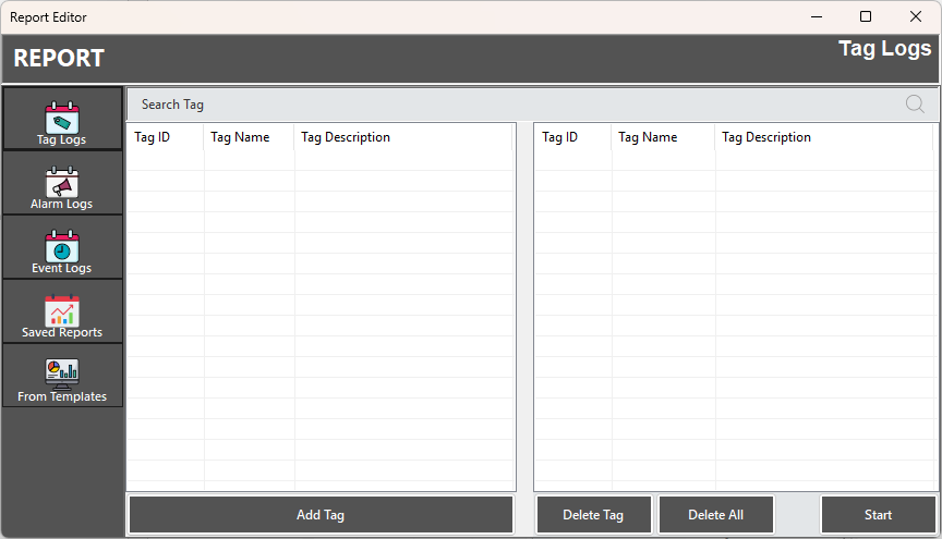
Figure 71 – Report Editor
3.9.1 Tag Logs
The component that keeps a record of the data collected by specific tags over time. These records include both real-time and historical data, allowing users to analyze system performance, identify trends, and detect issues.
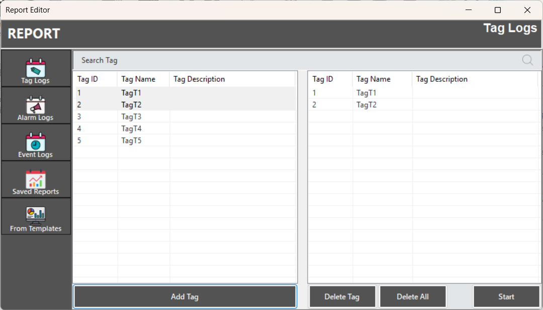
Figure 72 - Report Editor
To record tag data, the "Log Status" parameter in the tag information must be set to "Periodic." Tags with the "No Log" setting will not appear in the "Tag Logs" editor. The data will be recorded for the duration specified in the "Log Time" parameter.
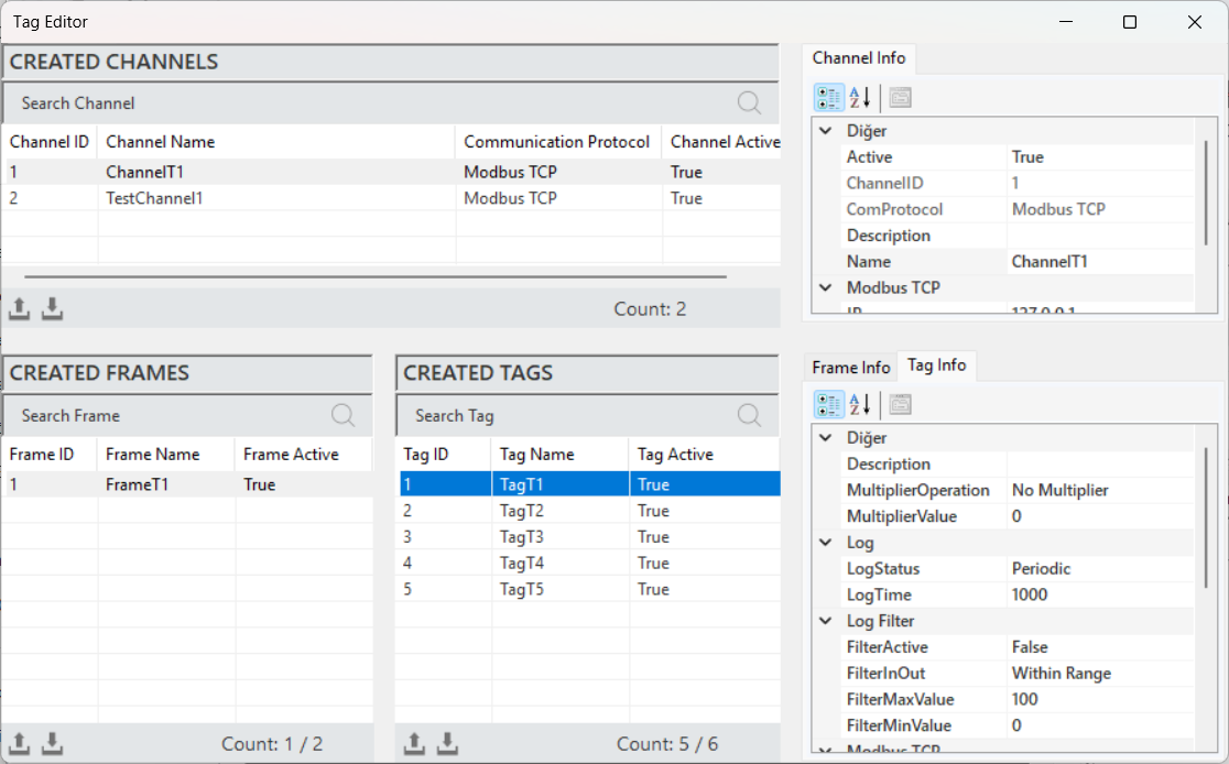
Figure 73 – Tag Log Creation
To begin reporting, relevant tags from the recorded tags are selected and added. After that, click "Start" to open the report editor.
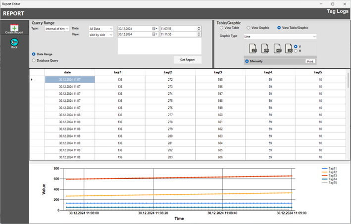
Figure 74 – Tag Logs
Users can access data records by utilizing search and filtering parameters to find specific data. There are two search methods available under the "Type" option for accessing data records. "Internal of time" is used to define a specific time range, while "Last" is used to access the most recent data within a defined period.
Parameters
Interval of Time
The "interval of time" within the "Query Range" is a parameter used to define a specific time period. This parameter allows users to select a specific start and end date or time when querying data.
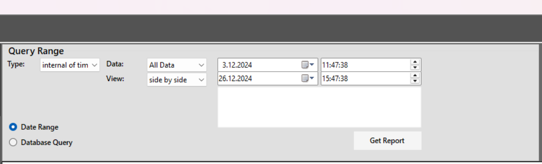
Figure 75 – Filter Parameters
“Type” > “internal of time” is selected:
Data: Determines whether to select al lor statistical data.
View: Specifies whether the data should be displayed side by side or one below the other.
Date Range: The process of accessing data records using editor parameters.
Database Query: The process of performing a database query using a script command.
Get Report: The command used to retrieve data.
Last
The "last" option within the "Query Range" allows users to access the most recent data over a specified period. This parameter is commonly used during data analysis when users need to quickly review the latest data or trends. It helps to focus on recent records or events that are critical for decision-making or system performance monitoring.
When the query range is selected as "Last," the "Period" and "Time" parameters will appear. These parameters are used to access data records within the specified time range and desired frequency.
Period: Defines the specific duration for which data records will be retrieved. This can refer to hours, days, weeks, etc.
Time: Refers to the exact point or window in time within which the data should be retrieved based on the period selected.
These parameters allow users to focus on the most relevant and recent data for analysis.
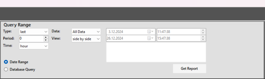
Figure 76 – Filter Parameters
Table/Graphic Panel
In the reporting editor, three types of panel view options are available, allowing for the analysis and interpretation of data in different formats. These options are as follows:
View Table: It is the presentation of data arranged in rows and columns.
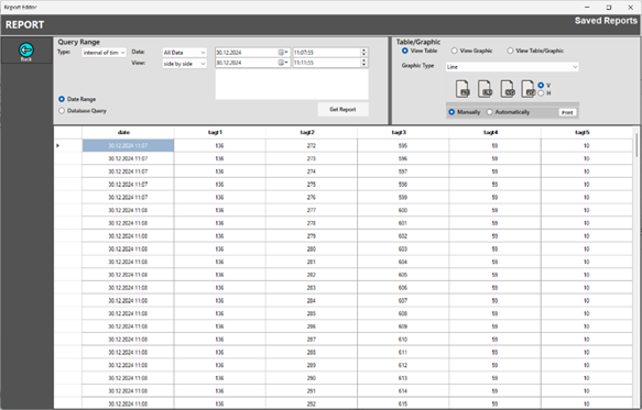
Figure 77 – Table View
View Graphic: It is the visual representation of data.
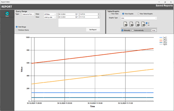
Figure 78 – Graphic View
View Table/Graphic: It is a view option that presents both table and graph formats together.
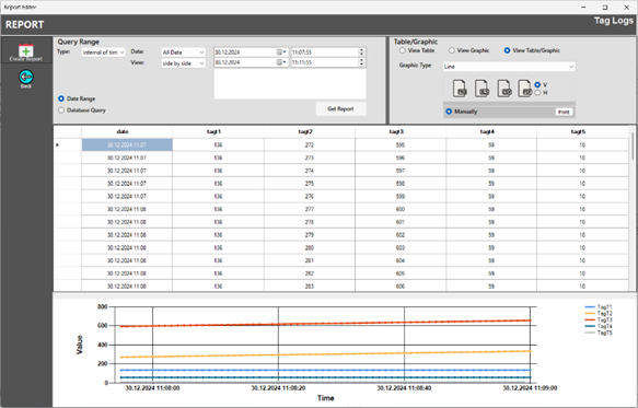
Figure 79 – Table/Graphic View
Each view offers different advantages for data analysis. All parameter descriptions are provided in the table below.
Report Output
After analyzing the data collected over a specific time period or under certain conditions, the process of generating a report is initiated. This report serves as a document in which users compile and gather relevant data. When exporting the report, users can choose between different formats. The output formats available in the editor are shown in the image below.
Reports can be generated through both manual and automatic methods. The manual report function is available for all reports. To generate the output, users click on "Print," and the system sends the records on the report screen to the pre-configured printer in PDF format for printing.
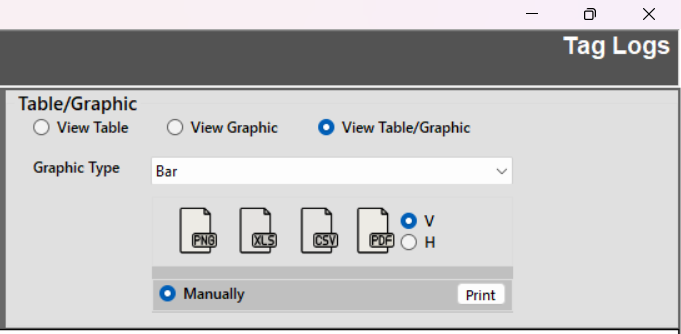
Figure 80 – Output Parameters
The parameter details are as follows:
Graphic Type: Determines the type of graphic for the data.
PNG: Generates a graphic output in PNG format.
XLS: Generates an output of the data in XLSX format.
CSV: Generates an output of the data in CSV format.
PDF: Generates an output of the data in PDF format.
V/H: Determines whether the table in generated output should be horizontal (H) or vertical (V).
Manually: Option to create a report manually.
Automatically: Automatically generates and outputs saved reports at scheduled times.
Print: Send the generated report to a connected printer and performs the printing process
Automatic Output
The automatic output function can only be used with saved reports. To automatically generate a report output, select from the saved reports for which this is desired. When the "Automatically" option is activated, the “Set” parameter will appear.
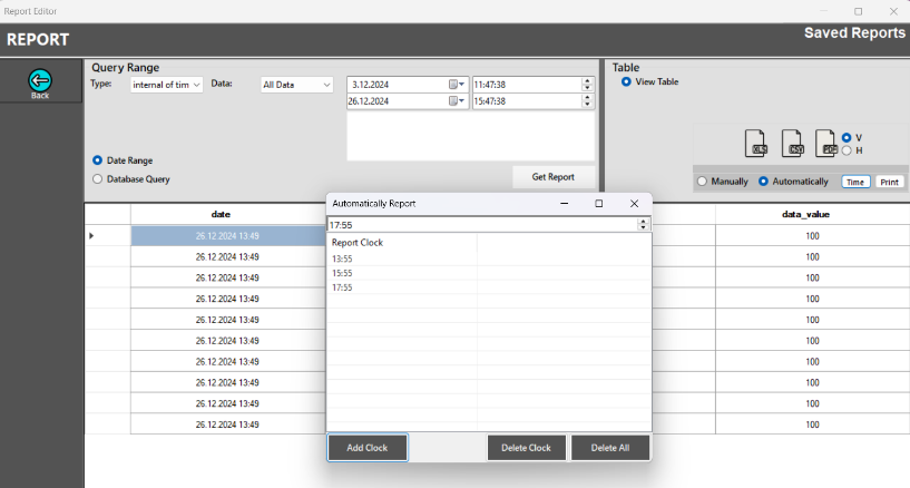
Figure 81 – Automatic Output
In the opened window, the hours for which the output is to be generated are added. At the specified date and time, the system will automatically generate the reports and perform the output process. The steps for this procedure are shown in the image below.
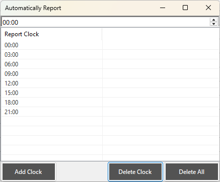
Figure 82 – Automatic Output
3.9.2 Alarm Logs
It functions as a component that keeps a record of alarms. These records include labels indicating the time of occurrence, type, and source of the alarms. To perform an alarm analysis, relevant alarm(s) are selected from the recorded alarms, added, and the report editor is opened by clicking "Start".
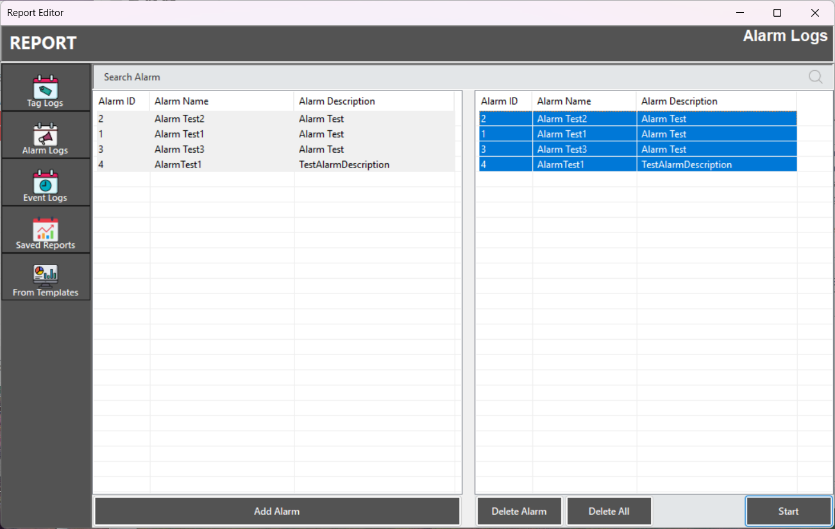
Figure 83 - Alarm Editor
In the opened screen, a time range is specified, and the selected alarm data is retrieved. The records will be displayed in a table format. These records can be exported in different formats.
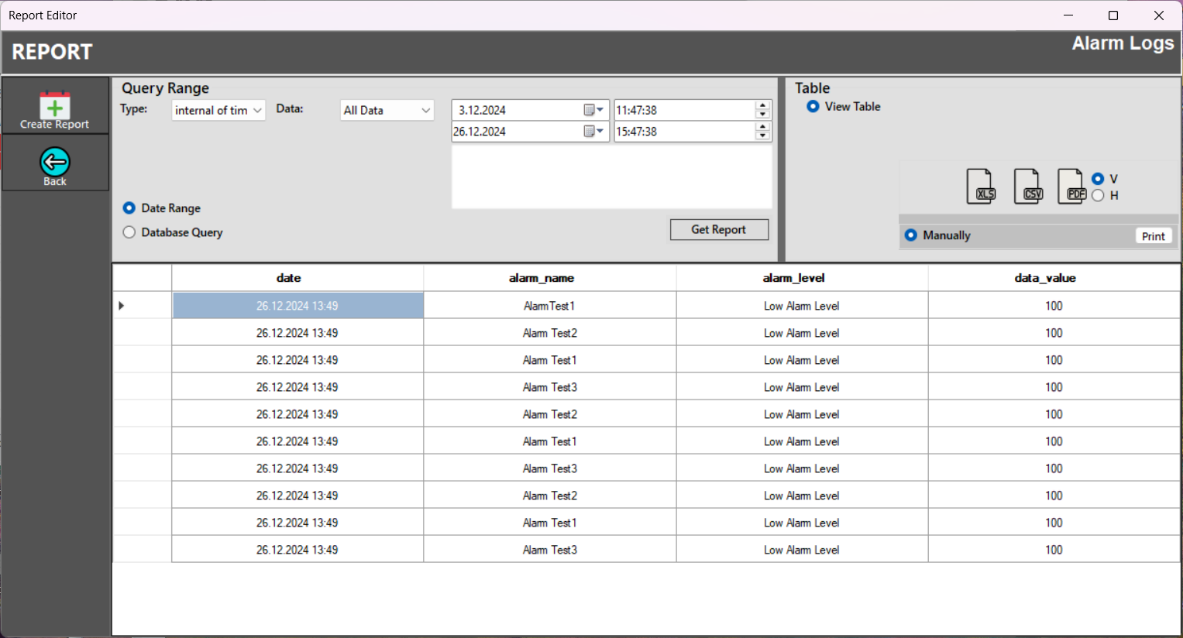
Figure 84 - Alarm Reports
Database Query
Database Query allows for direct data retrieval from the database, providing access to real-time and up-to-date information. To search for records based on specific alarm information, a script can be written to access the alarm records. The results of a database query using an example script are shown in the image below.

Figure 85 – Database Query
3.9.3 Event Logs
It is a component that records important events occurring in SCADA systems. These records include events such as user interactions with the system, system startups, and shutdowns. By entering a time range, event records can be accessed. The records are displayed in a table view and can be exported in different formats.
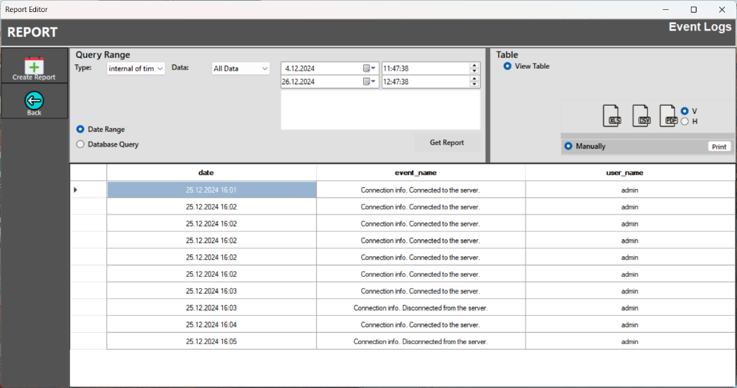
Figure 86 – Event Logs
3.9.4 Saved Reports
It refers to the reporting parameters that have been previously created and saved in the SCADA system. It allows users to quickly view, review, and, if necessary, reuse reports generated in the past.
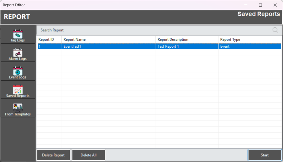
Figure 87 – Saved Reports
To access the saved reports, click on "Saved Reports" in the report editor. A list of saved reports will be displayed. Select the relevant report, and click "Start" to begin accessing the report data. The system will retrieve the data records based on the available information.
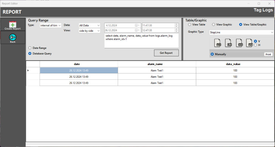
Figure 88 – Saved Reports
Saving a Reports
After entering the necessary information, the "Create Report" option is used to save the report as a draft.
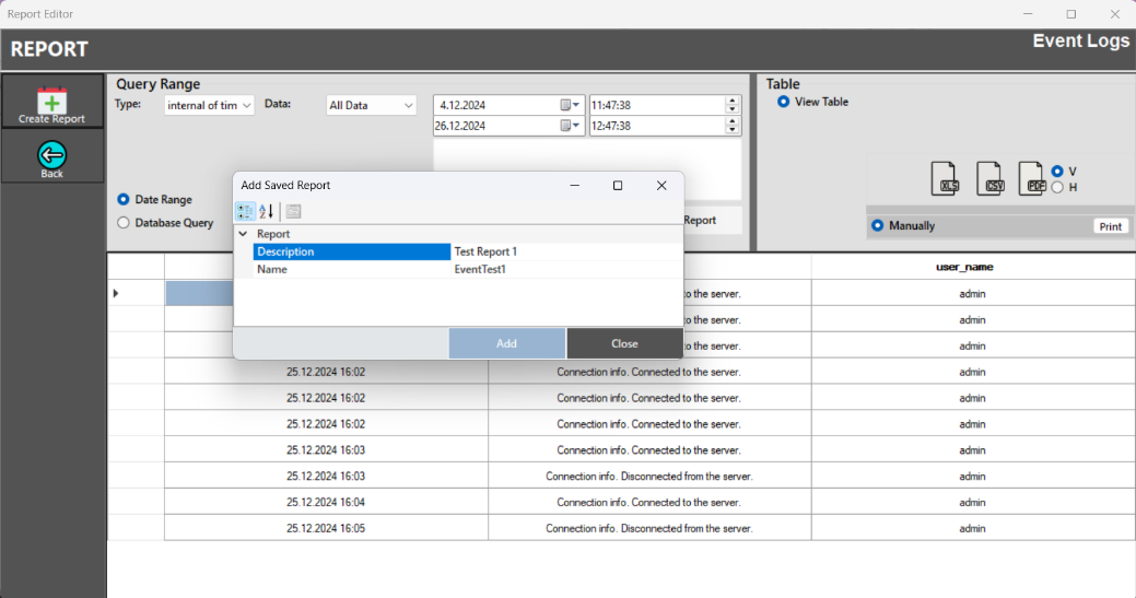
Figure 89 – Save a Report
3.9.5 Report Templates
Standard report templates are used for data analysis and reporting in the SCADA system. These templates are in .xlsx format and can be selected and saved to a local folder. Reports are created by editing the template.
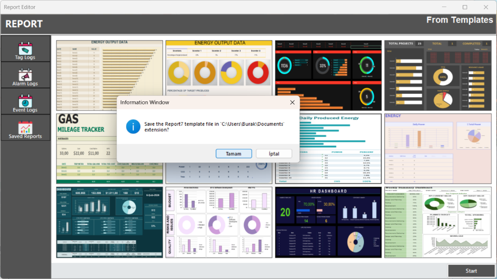
Figure 90 – Report Templates