Communication Protocols
4. COMMUNICATION PROTOCOLS
The communication protocols are essential for the OEE software to communicate with field devices. This section includes the protocol definitions and their specific settings. Channels determine the communication methods used for data transmission, ensuring the integrity of the system.
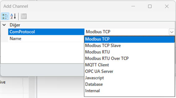
Figure 56 – Communication Protocols
All communication protocols are explained in detail in the following sections, and the processes of creating channels, frames, and tags based on these protocols are also covered.
4.1 Modbus TCP Protocol
The Modbus TCP Client acts as a client that communicates with a server via the Modbus TCP protocol. The Modbus TCP client sends requests to a Modbus TCP server and receives responses from it. The server is typically a device (e.g., a PLC), and the client is an application that reads or writes data from this device
Modbus TCP Channel Creation
To add a channel in the Modbus TCP protocol, right-click in the "Created Channels" area in the Tag Editor and select "Add Channel."
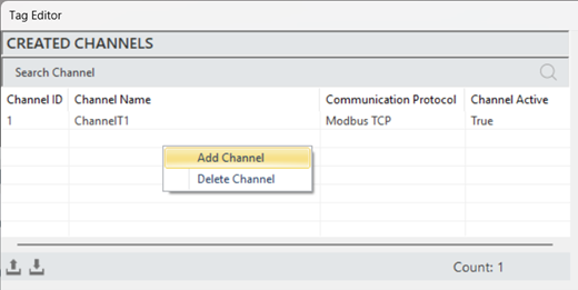
Figure 57 – Creating a Modbus TCP Channel
In the opened window, select the communication protocol as "Modbus TCP," then specify the channel name to add the new channel.
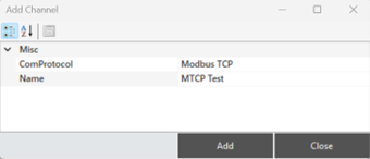
Figure 58 – Creating a Modbus TCP Channel
Modbus TCP Channel Structure
To access and modify channel information, when a channel is selected, all details are displayed in the "Channel Info" panel.
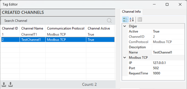
Figure 59 – Modbus TCP Channel Info
The parameter descriptions for the channel information are provided in the table below.
“Active” | Determines whether the frame is active or inactive. |
“Channel ID” | A unique identifier for the channel. |
“Com Protocol” | Communication type information. Set when the channel is created. |
“Description” | A description of the channel, defined according to the requirements. |
“IP” | The IP address for communication. |
“Port” | The port information for communication. |
“Request Time” | The communication data response timeout in milliseconds. |
Table 9 – Modbus TCP Channel Parameters
Modbus TCP Frame Creation
The process of defining a new frame to structure and manage data. To create a frame, a channel must first be created. A channel is selected, and by right-clicking in the "Created Frames" section, the "Add Frame" option is clicked.
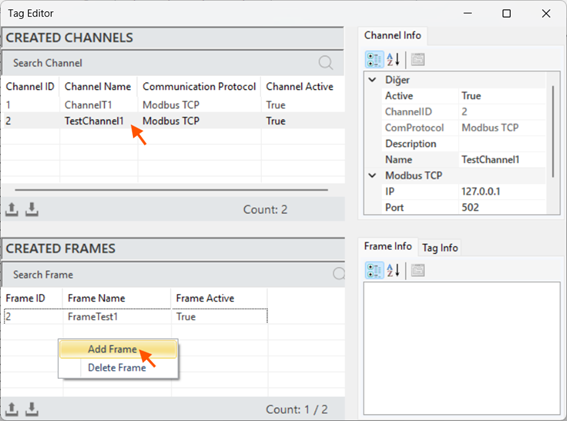
Figure 60 – Creating a Modbus TCP Frame
After entering the frame information in the opened window, click "Add" to create the frame.
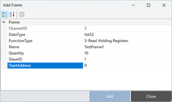
Figure 61 – Creating a Modbus TCP Frame
Modbus TCP Frame Structure
When a frame is selected, all information is displayed in the "Frame Information" panel for access and editing.
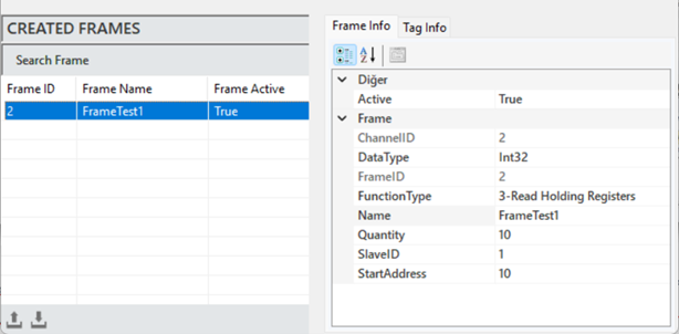
Figure 62 – Modbus TCP Frame Info
The explanations of these parameters are provided in the table below.
“Active” | Determines whether the frame is active or inactive. |
“Channel ID” | The unique channel information to which the frame is associated. |
“Data Type” | The data type of the frame. |
“Function Type” | The function type of the frame. |
“Name” | The name of the frame. |
“Quantity” | The number of data (tags) in the frame. |
“Slave ID” | The device ID for communication. |
“Start Address” | The starting address of the first data in the frame. |
Table 10 – Modbus TCP Frame Parameters
·
Modbus TCP Tag Creation
The process of creating a new tag that represents a specific measurement or control data. To create a tag, a frame must first be created. Once a frame is selected, right-click on the "Created Tags" area and click on "Add Tag".
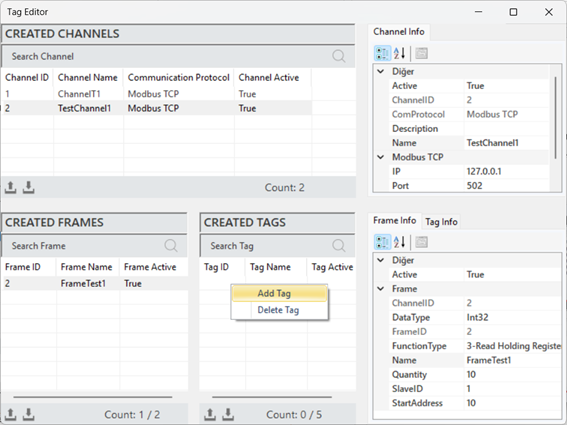
Figure 63 – Creating a Modbus TCP Tag
Once the tag information is entered in the opened window, click "Add" to create the tag.
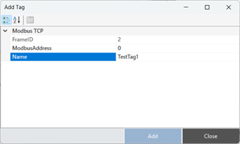
Figure 64 – Creating a Modbus TCP Tag
Modbus TCP Tag Structure
To access and edit the tag information, when a tag is selected, all the details are displayed in the "Tag Info" panel.
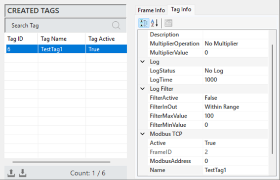
Figure 65 – Modbus TCP Tag Info
The explanations of these parameters are presented in the table below.
"Description" | This is the label information field |
"Multiplier Operation" | Used to perform any mathematical operation on the label data |
"Multiplier Value" | Specifies the value for the operation to be applied to the label |
"Log Status" | Indicates the log status of the label. To activate, set it to “Periodic”, and to deactivate, set it to “No Log” |
"Log Time" | The time duration for recording label data, specified in milliseconds. |
"Filter Active" | If filtering is required while recording label data, this command is activated. |
"FilterInOut" | Defines whether the filter should be applied to values inside or outside the specified range. |
"FilterMaxValue" | Specifies the maximum value in the created filter. |
"FilterMinValue" | Specifies the minimum value in the created filter. |
"Active" | Determines the active/inactive status of the label. |
"Frame ID" | The identification information of the selected frame. |
"ModbusAddress" | Specifies the address for communication of the label. |
"Name" | This is the label name. |
"Tag ID" | The unique identifier number that defines the channel in the figure. |
Table 11 – Modbus TCP Tag Parameters
4.2 Modbus TCP Slave Protocols
The Modbus TCP Slave protocol operates over TCP/IP (Transmission Control Protocol/Internet Protocol) to facilitate data exchange between a "master" device and one or more "slave" devices.
Modbus TCP uses 16-bit words for data transmission, employing structured data formats such as registers and digital inputs/outputs.
Modbus TCP Slave Channel Creation
To add a channel in the Modbus TCP Slave protocol, right-click within the "Created Channels" area and select "Add Channel”.
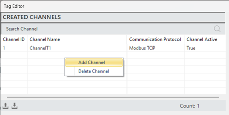
Figure 66 – Creating a Modbus TCP Slave Channel
In the window that opens, select the communication protocol as "Modbus TCP Slave," specify the channel name, and then add the new channel.
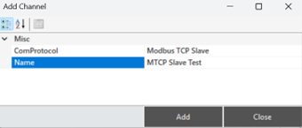
Figure 67 – Creating a Modbus TCP Slave Channel
Modbus TCP Slave Channel Structure
When a channel is selected to access and make adjustments to its information, all details are reflected in the "Channel Information" panel.
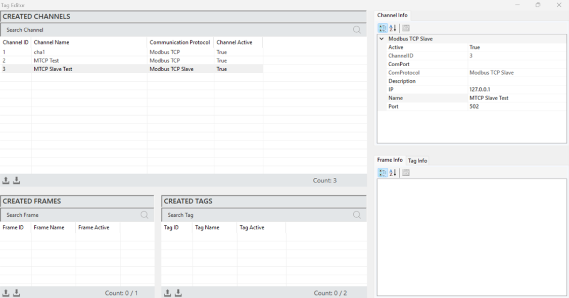
Figure 68 – Modbus TCP Slave Channel Info
The parameter descriptions are presented in the table below.
“Active” | Determines the active/inactive status of the channel. |
“Channel ID” | A unique identification number that defines the channel in a figure. |
“Com Protocol” | The communication type. It is specified when the channel is created. |
“Description” | The channel description. It is defined based on the requirements. |
“IP” | The IP address through which communication will be established. |
“Port” | The port information through which communication will be established. |
“Request Time” | The communication data response timeout, specified in milliseconds. |
Table 12 – Modbus TCP Slave Channel Parameters
Modbus TCP Slave Frame Creation
It is the process of defining a new frame to organize and manage the data structure. To create a frame, a channel must first be created. A channel is selected, and then right-clicking in the "Created Frames" area allows for adding a frame.
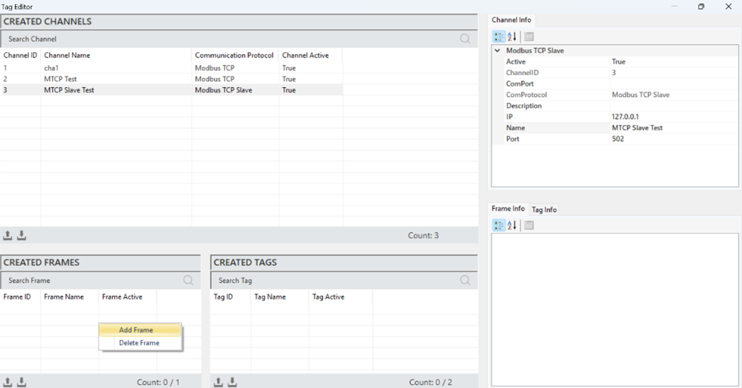
Figure 69 – Creating a Modbus TCP Slave Frame
In the window that opens, after entering the frame details, click "Add" to create the frame.
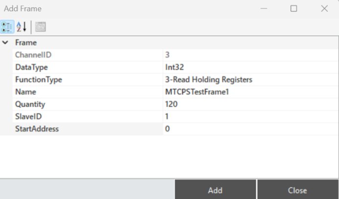
Figure 70 – Creating a Modbus TCP Slave Channel
Modbus TCP Slave Frame Structure
When a frame is selected to access and make adjustments to its information, all details are reflected in the "Frame Information" panel.
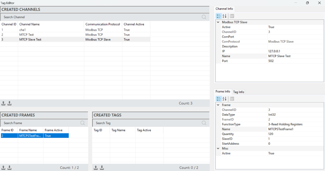
Figure 71 – Modbus TCP Slave Frame Info
The parameter descriptions are presented in the table below.
“Active” | Determines the active/inactive status of the frame. |
“Channel ID” | A unique identification number that defines the frame in a figure. |
“Data Type” | Specifies the data type of the frame. |
“Function Type” | Specifies the function type of the frame. |
“Name” | The name of the frame. |
“Quantity” | The number of data (tags) in the frame. |
“Slave ID” | The identification number of the device to communicate with. |
“Start Address” | The address where the first data in the frame is located, and the starting address. |
Table 13 – Modbus TCP Slave Frame Parameters
·
Modbus TCP Slave Tag Creation
It is the process of creating a new label that represents a specific measurement or control data. To create a label, a frame must first be created. A frame is selected, and then right-clicking in the "Created Tags" area allows for adding a label.
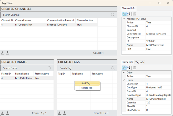
Figure 72 – Creating a Modbus TCP Slave Tag
In the window that opens, after entering the label details, click "Add" to create the label.
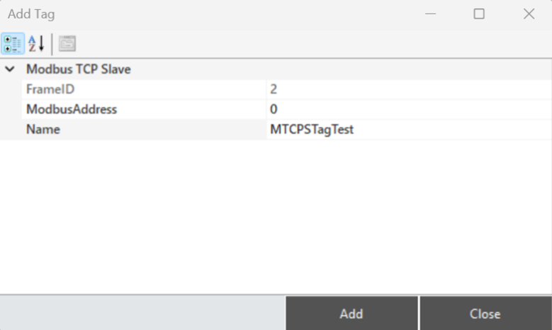
Figure 73 – Creating a Modbus TCP Slave Tag
Modbus TCP Slave Tag Structure
When a label is selected to access and make adjustments to its information, all details are reflected in the "Label Information" panel.
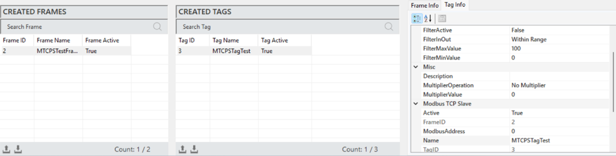
Figure 74 – Modbus TCP Slave Tag Info
The parameter descriptions are presented in the table below.
"Description" | This is the label information field. |
"Multiplier Operation" | Defines the mathematical operation. |
"Multiplier Value" | Converts raw data into meaningful measurements using a multiplier. |
"Log Status" | Specifies the data logging status of the label. |
"Log Time" | The duration of the data logging period, specified in milliseconds. |
"Filter Active" | Enables the filtering function for label data recording. |
"FilterInOut" | Defines the filter function (whether the values are inside or outside the specified range). |
"FilterMaxValue" | Specifies the maximum value for filtering. |
"FilterMinValue" | Specifies the minimum value for filtering. |
"Active" | Determines the active/inactive status of the label. |
"Frame ID" | The unique identification of the selected frame. |
"ModbusAddress" | Specifies the address used for communication of the label. |
"Name" | The name of the label. |
"Tag ID" | The unique identification number that defines the label in a figure. |
Table 14 – Modbus TCP Slave Tag Parameters
4.3 Modbus RTU Protocols
The Modbus RTU protocol is a serial communication protocol used for data exchange in industrial automation systems. This protocol operates over serial communication methods such as RS-232 or RS-485, enabling data exchange between a master device and one or more slave devices. Modbus RTU uses 16-bit words for data transmission and works with structured data formats like registers and digital inputs/outputs.
Modbus RTU Channel Creation
To add a channel in the Modbus RTU protocol, right-click within the "Created Channels" area in the tag editor and select "Add Channel.
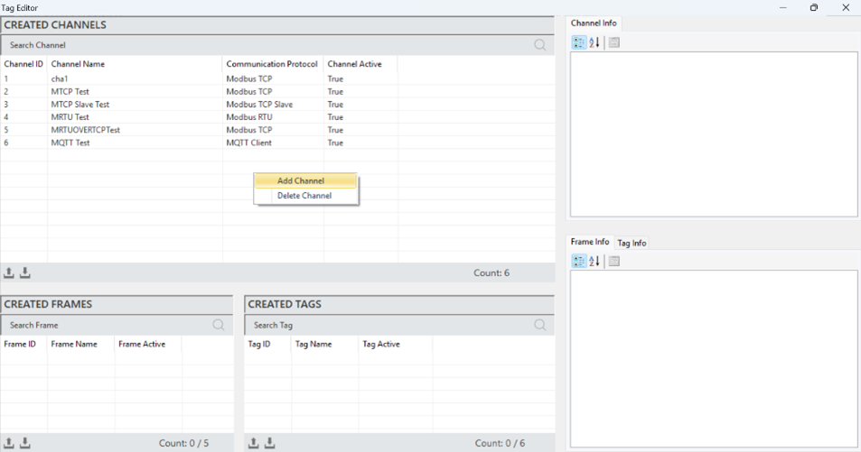
Figure 75 – Creating a Modbus RTU Slave Channel
In the window that opens, select the communication protocol as "Modbus RTU," specify the channel name, and then add the new channel.
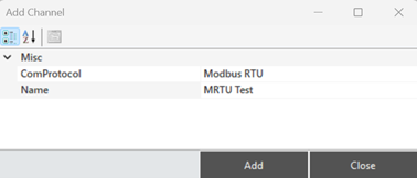
Figure 76 – Creating a Modbus RTU Slave Channel
Modbus RTU Channel Structure
When a channel is selected to access and make adjustments to its information, all details are reflected in the "Channel Information" panel.
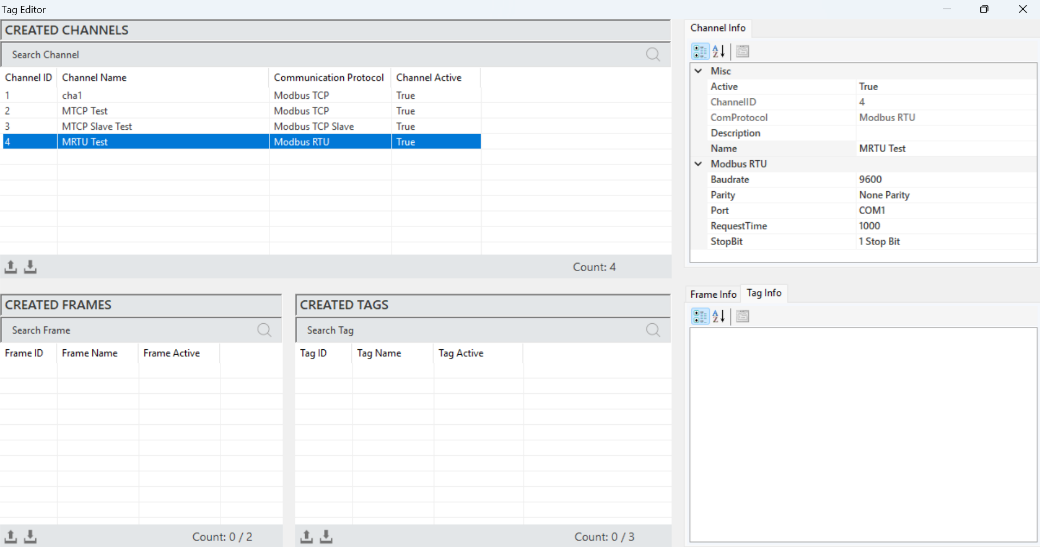
Figure 77 – Modbus RTU Channel Info
The parameter descriptions are presented in the table below.
“Active” | Determines the active/inactive status of the channel. |
“Channel ID” | A unique identification number that defines the channel in a figure. |
“Com Protocol” | Specifies the communication type. It is defined when the channel is created. |
“Description” | The channel description. |
“Name” | The name of the channel. |
“Baudrate” | A measure that specifies the data transmission speed. |
“Parity” | Adds an extra bit for error checking in data transmission. |
“Port” | Specifies the port used for communication. |
“Request Time” | The communication data response timeout, specified in milliseconds. |
“Stop Bit” | Specifies the end of the data frame. |
Table 15 – Modbus RTU Channel Parameters
Modbus RTU Frame Creation
It is the process of defining a new frame to organize and manage the data structure. To create a frame, a channel must first be created. A channel is selected, and then right-clicking in the "Created Frames" area allows for adding a frame.
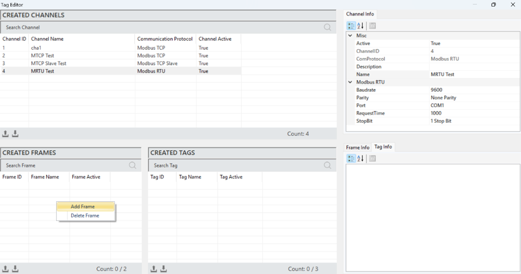
Figure 78 – Creating a Modbus RTU Slave Frame
In the window that opens, after entering the frame details, click "Add" to create the frame.
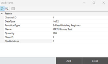
Figure 79 – Creating a Modbus RTU Slave Frame
Modbus RTU Frame Structure
When a frame is selected to access and make adjustments to its information, all details are reflected in the "Frame Information" panel.
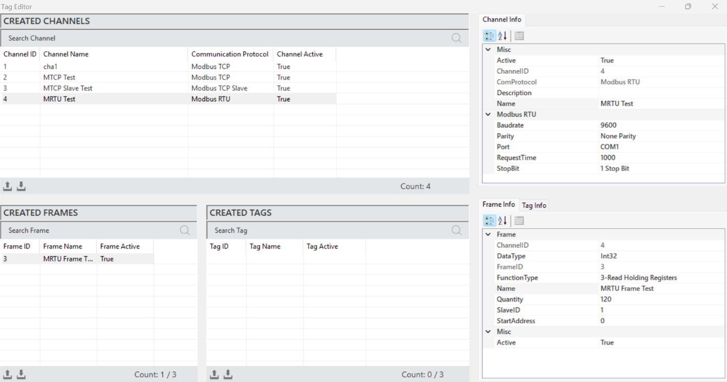
Figure 80 – Modbus RTU Frame Info
The parameter descriptions are presented in the table below.
“Active” | Determines the active/inactive status of the frame. |
“Channel ID” | A unique identification number that defines the frame in a figure. |
“Data Type” | Specifies the data type of the frame. |
“Function Type” | Specifies the function type of the frame. |
“Name” | The name of the frame. |
“Quantity” | The number of data (tags) in the frame. |
“Slave ID” | The identification number of the device to communicate with. |
“Start Address” | The address where the first data in the frame is located, and the starting address. |
Table 16 – Modbus RTU Frame Parameters
Modbus RTU Tag Creation
It is the process of creating a new label that represents a specific measurement or control data. To create a label, a frame must first be created. A frame is selected, and then right-clicking in the "Created Tags" area allows for adding a label.
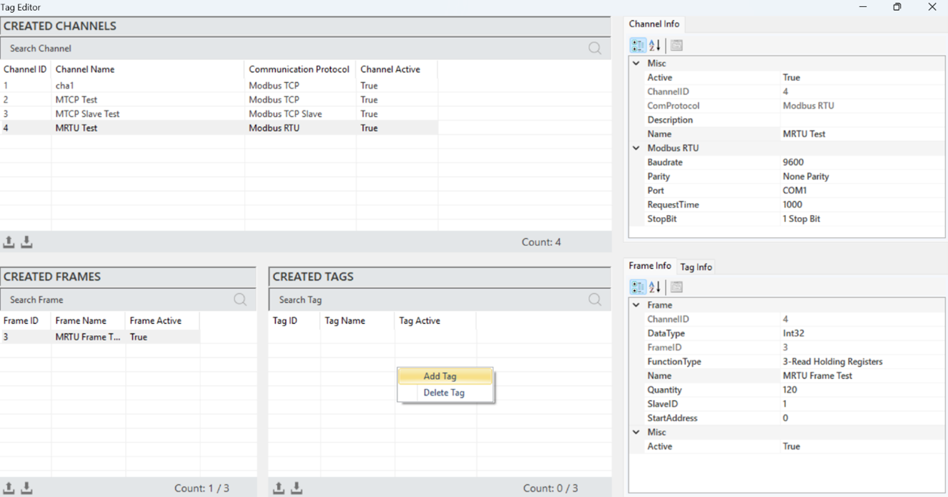
Figure 81 – Creating a Modbus RTU Tag
In the window that opens, after entering the label details, click "Add" to create the label.
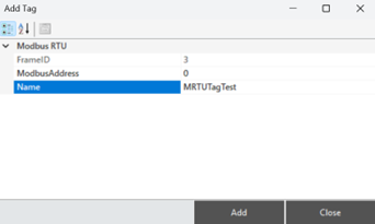
Figure 82 – Creating a Modbus RTU Tag
Modbus RTU Tag Structure
When a label is selected to access and make adjustments to its information, all details are reflected in the "Label Information" panel.
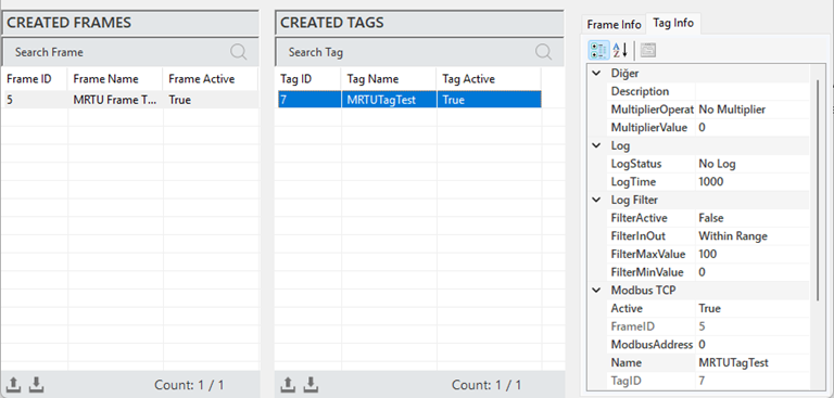
Figure 83 – Modbus RTU Tag Info
The parameter descriptions are presented in the table below.
"Description" | The label information field. |
"Multiplier Operation" | Defines the mathematical operation. |
"Multiplier Value" | Converts raw data into meaningful measurements using a multiplier. |
"Log Status" | Specifies the data logging status of the label. |
"Log Time" | The data logging period, specified in milliseconds. |
"Filter Active" | Enables the filtering function for label data recording. |
"FilterInOut" | Defines the filter function for values within or outside the range |
"FilterMaxValue" | Specifies the maximum value for filtering. |
"FilterMinValue" | Specifies the minimum value for filtering. |
"Active" | Determines the active/inactive status of the label. |
"Frame ID" | The unique identification number of the selected frame. |
"ModbusAddress" | Specifies the address used for communication of the label. |
"Name" | The name of the label. |
"Tag ID" | The unique identification number that defines the label in a figure. |
Table 17 – Modbus RTU Tag Parameters
4.4 Modbus RTU OVER TCP Protocol
Modbus RTU is a structure that enables the transmission of Modbus RTU messages over the TCP/IP (Transmission Control Protocol/Internet Protocol) communication protocol. It allows devices to connect over an Ethernet network.
Modbus RTU OVER TCP Channel Creation
To add a channel in the Modbus RTU OVER TCP Slave protocol, right-click within the "Created Channels" area and select "Add Channel".
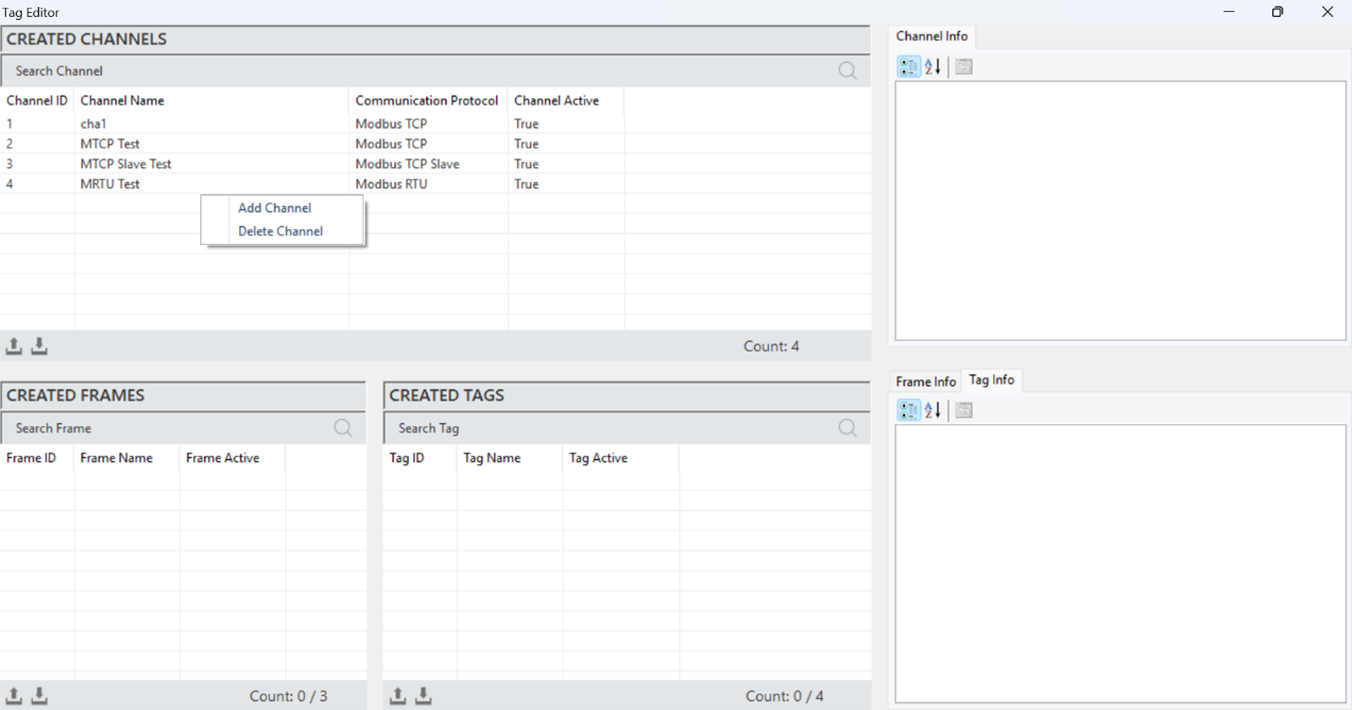
Figure 84 – Creating a Modbus RTU OVER TCP Channel
In the window that opens, select the communication protocol as "Modbus RTU OVER TCP," specify the channel name, and then add the new channel.
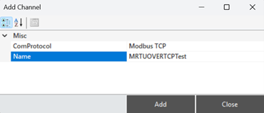
Figure 85 – Creating a Modbus RTU OVER TCP Channel
Modbus RTU OVER TCP Channel Structure
When a channel is selected to access and make adjustments to its information, all details are reflected in the "Channel Information" panel.
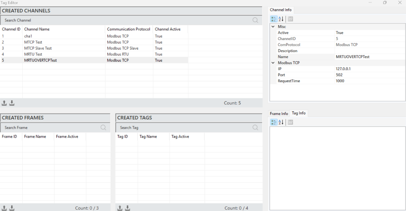
Figure 86 – Modbus RTU OVER TCP Channel Info
The parameter descriptions are presented in the table below.
“Active” | Determines the active/inactive status of the channel. |
“Channel ID” | A unique identification number that defines the channel in a figure. |
“Com Protocol” | Specifies the communication type. It is defined when the channel is created. |
“Description” | The channel description, defined according to the need. |
“IP” | Specifies the IP address for communication. |
“Port” | Specifies the port used for communication. |
“Request Time” | The communication data response timeout, specified in milliseconds. |
Table 18 – Modbus RTU OVER TCP Channel Parameters
·
Modbus RTU OVER TCP Frame Creation
It is the process of defining a new frame to organize and manage the data structure. To create a frame, a channel must first be created. A channel is selected, and then right clicking in the "Created Frames" area allows you to add a frame.
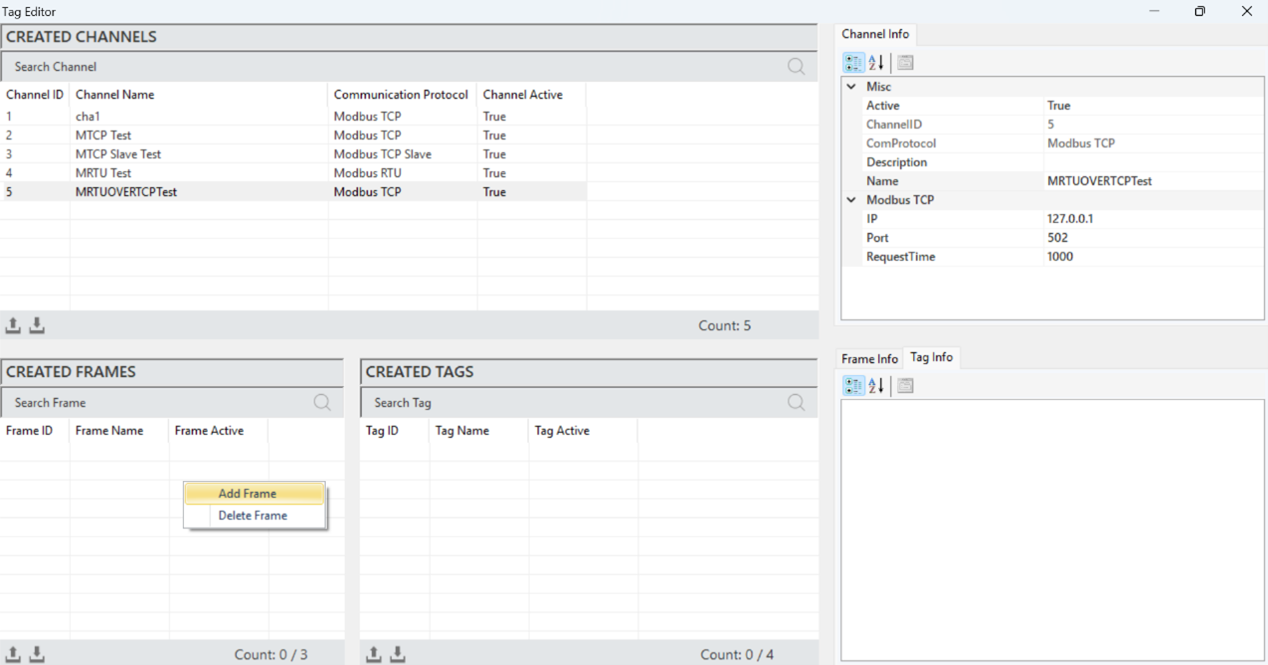
Figure 87 – Creating a Modbus RTU OVER TCP Frame
In the window that opens, after entering the frame details, click "Add" to create the frame.
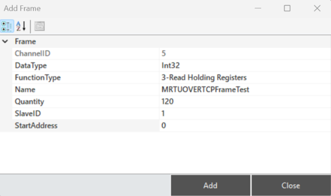
Figure 88 – Creating a Modbus RTU OVER TCP Frame
Modbus RTU OVER TCP Frame Structure
When a frame is selected to access and make adjustments to its information, all details are reflected in the "Frame Information" panel.
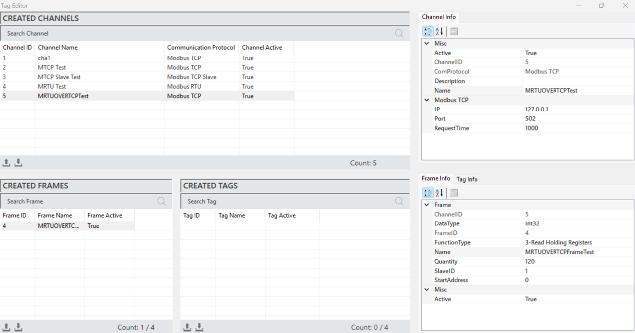
Figure 89 – Modbus RTU OVER TCP Frame Info
The parameter descriptions are presented in the table below.
“Active” | Determines the active/inactive status of the frame. |
“Channel ID” | A unique identification number that defines the frame in a figure. |
“Data Type” | Specifies the data type of the frame. |
“Function Type” | Specifies the function type of the frame. |
“Name” | Name of the frame. |
“Quantity” | The number of data (tags) in the frame. |
“Slave ID” | The identification number of the device for communication. |
“Start Address” | The address of the first data in the frame, also the starting address |
Table 19 – Modbus RTU OVER TCP Channel Parameters
·
Modbus RTU OVER TCP Tag Creation
It is the process of creating a new label that represents a specific measurement or control data. To create a label, a frame must first be created. A frame is selected, and then right-clicking in the "Created Tags" area allows you to add a label.
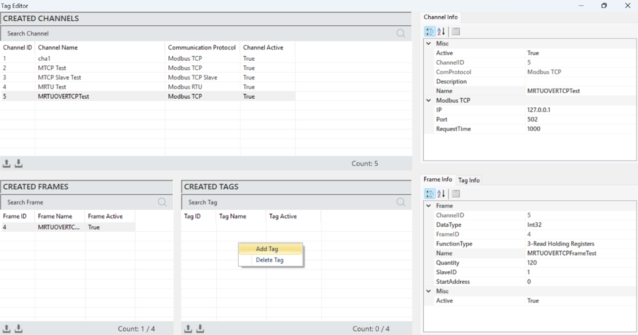
Figure 90 – Creating a Modbus RTU OVER TCP Tag
In the window that opens, after entering the label details, click "Add" to create the label.

Figure 91 – Creating a Modbus RTU OVER TCP Tag
Modbus RTU OVER TCP Tag Structure
When a label is selected to access and make adjustments to its information, all details are reflected in the "Label Information" panel.
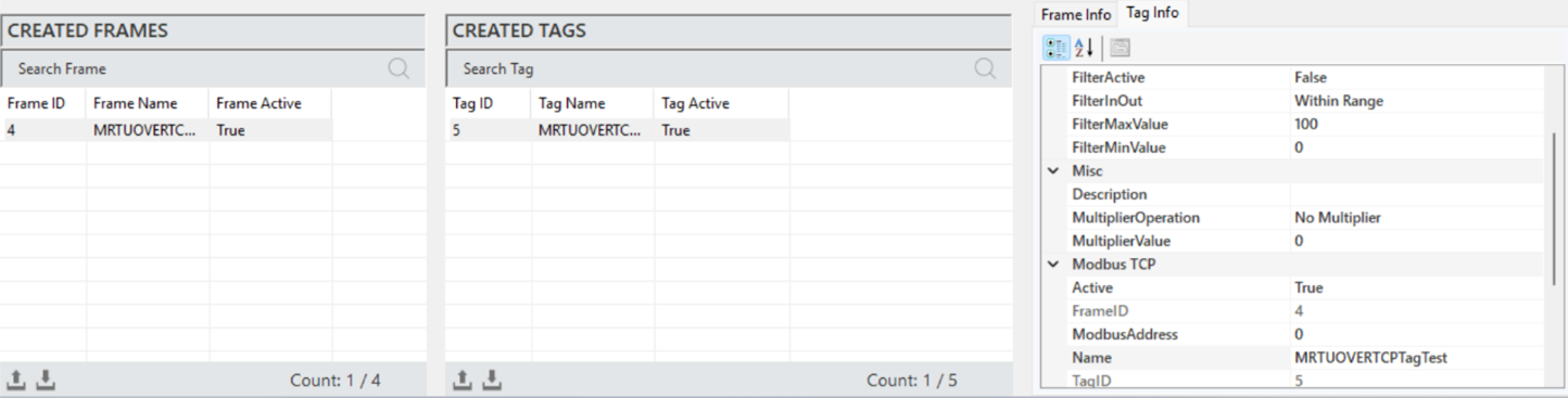
Figure 92 – Modbus RTU OVER TCP Tag Info
The parameter descriptions are presented in the table below.
"Description" | The label information field. |
"Multiplier Operation" | Used to perform any mathematical operation on the label data. |
"Multiplier Value" | Specifies the value in the operation to be applied to the label. |
"Log Status" | Indicates the label's log status. Select "Periodic" to activate, or "No Log" to deactivate |
"Log Time" | The duration for recording label data, specified in milliseconds. |
"Filter Active" | Activates the filtering function when label data is being recorded. |
"FilterInOut" | Defines whether the filter value should be within or outside the specified range. |
"FilterMaxValue" | Specifies the maximum value in the filter. |
"FilterMinValue" | Specifies the minimum value in the filter. |
"Active" | Determines the active/inactive status of the label. |
"Frame ID" | The unique ID of the selected frame, automatically assigned by the editor |
"ModbusAddress" | Specifies the address for communication with the label. |
"Name" | The name of the label. |
"Tag ID" | The identification number that uniquely defines the label in a figure. |
Table 20 – Modbus RTU OVER TCP Channel Parameters
4.5 MQTT Client Protocol
The MQTT (Message Queuing Telemetry Transport) protocol is a communication protocol used for data exchange in IoT applications, known for its lightweight structure. Designed to operate on networks with low bandwidth, MQTT adopts the "publish/subscribe" model, enabling asynchronous data exchange between devices. The protocol operates through a central broker, where messages are sent, enhancing the scalability of the system.
4.5.1 Mosquitto
For effective communication via MQTT in the Proveris® OEE software, both the MQTT Broker and the OEE server must run on the same computer. This setup is critical for ensuring the seamless operation of the system’s data communication and control mechanisms.
In this context, it is essential to first install the Mosquitto program on the computer where the OEE server will be used. Mosquitto serves as the MQTT Broker, providing reliable data transmission between devices and facilitating the integration of systems.
4.5.2 Mosquitto Installation
To install the Mosquitto Broker, download the appropriate version from the official website or click here to access the download link. Once downloaded, begin the installation process on your computer.
In the installation wizard, click "Next" on the first page to proceed.
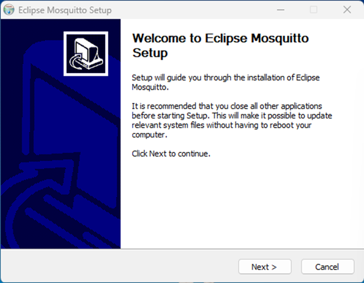
Figure 93 - Mosquitto Installation
Select the features you want to install for Mosquitto and click "Next" to proceed.
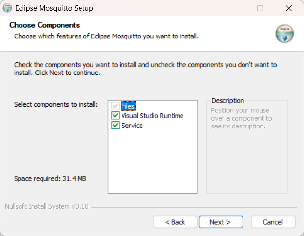
Figure 94 - Mosquitto Installation
Select the directory where you want to install Mosquitto and click "Install" to begin the installation process.
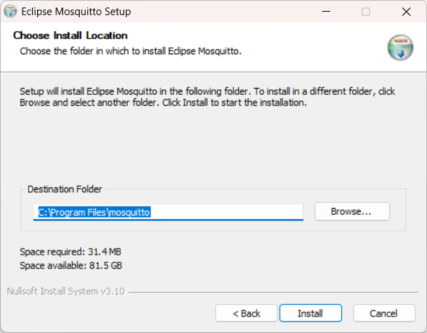
Figure 95 - Mosquitto Installation
The installation wizard will begin.
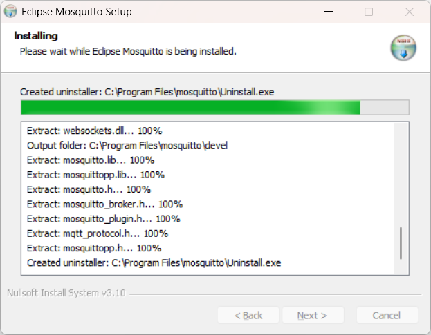
Figure 96 - Mosquitto Installation
Once the installation is complete, click “Finish” to exit the wizard.
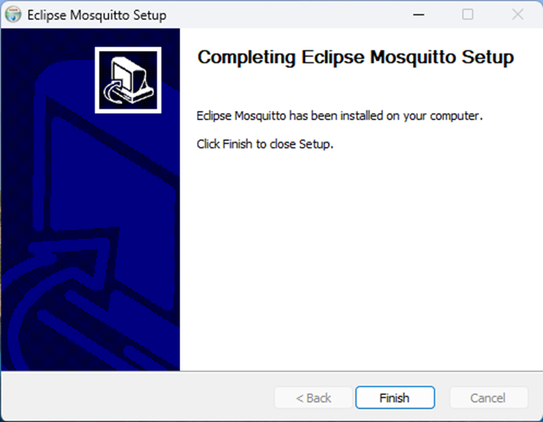
Figure 97 - Mosquitto Installatio
4.5.3 Mosquitto Configuration Settings
Configuring Mosquitto properly is crucial for its use within the Proveris® OEE system. Below are the key steps and settings:
The Mosquitto configuration file is typically located at /etc/mosquitto/mosquitto.conf. Open this file using a text editor.
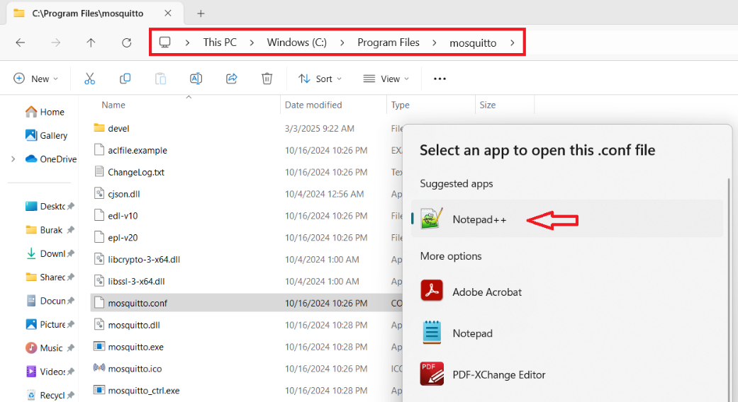
Figure 98 - Mosquitto Configuration
The file's appearance when opened in Notepad++ is as follows:
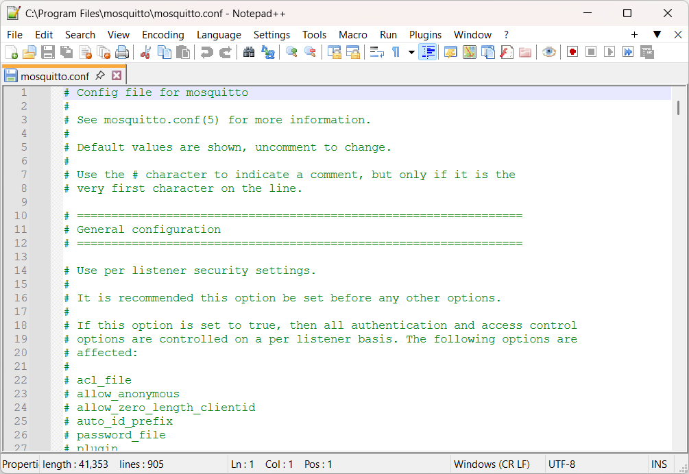
Figure 99 - Mosquitto Configuration
In the file, use the Ctrl+F command to find the "Security" section, and make the following changes under this heading:
For the security setting: Change the "false" value in the command “#allow_anonymous false” to “true”.
For the port setting: Add the command “#listener 1883” immediately below the line above.
By default, Mosquitto uses port 1883. If you wish to use a different port, you can specify it.
The appearance after these settings will be as follows:
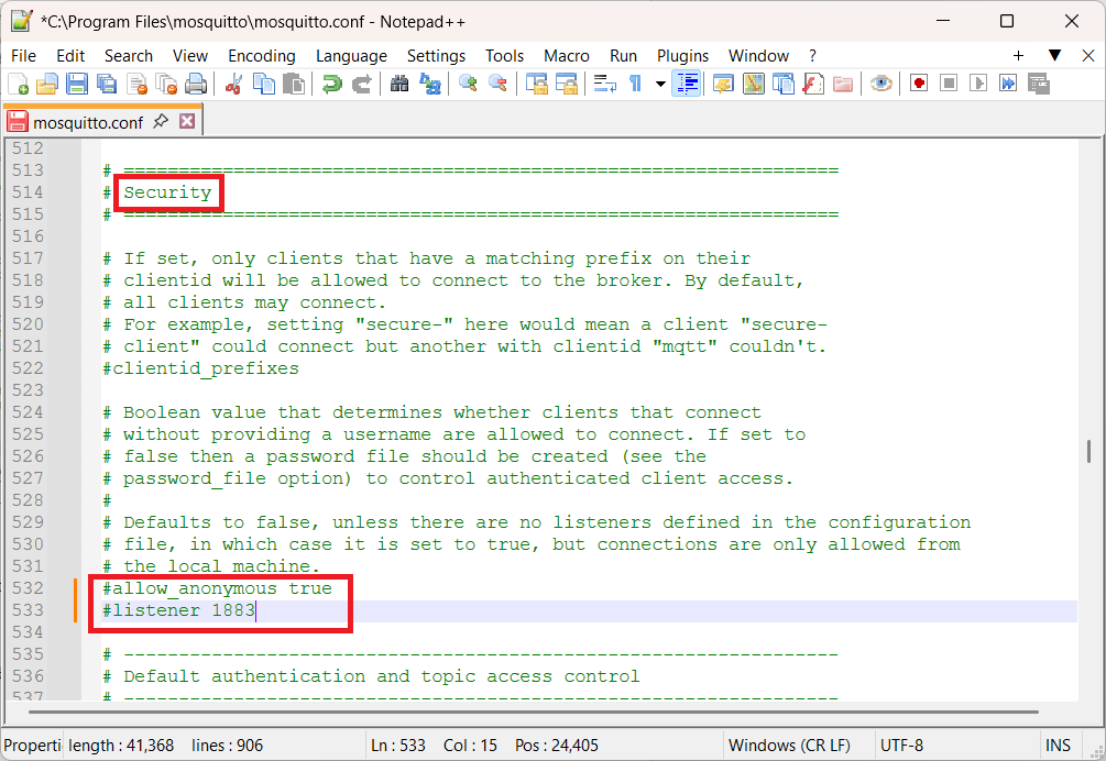
Figure 100 - Mosquitto Configuration
By following these steps, you can integrate Mosquitto with your Omnivex SCADA system, and the default MQTT port 1883 will be defined in the Broker settings as well.
After making the necessary changes, you can save the file and exit.
4.5.4 Running Mosquitto
Once the configuration settings are complete, follow these steps to run Mosquitto:
Go to Start > Search and type “cmd”. In the search results, right-click on Command Prompt and select Run as Administrator.
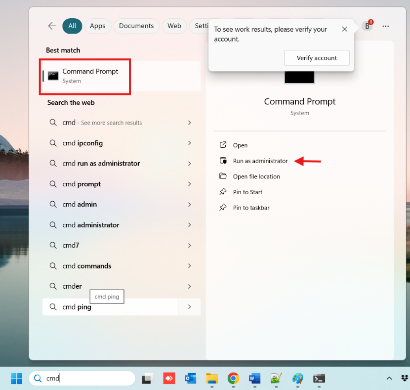
Figure 101 – Running Mosquitto
In the opened window, type the command “net start mosquitto” and press the Enter key. Once you receive the notification "Mosquitto Broker service has started successfully," Mosquitto will be running.
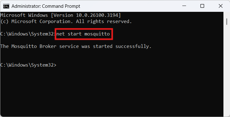
Figure 102 - Running Mosquitto
To stop Mosquitto, type the command "net stop mosquitto" in the Command Prompt window and press the Enter key. The program will stop, and you will receive the notification "Mosquitto Broker service has been stopped successfully".
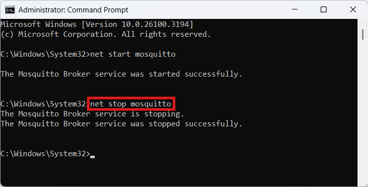
Figure 103 – Running Mosquitto
Creating an MQTT Client Channel
To add a channel in the MQTT Client protocol, right-click within the "Created Channels" area and select "Add Channel".

Figure 104 – Creating a MQTT Channel Channel
In the opened window, select the communication protocol "MQTT Client," specify the channel name, and then add the new channel.
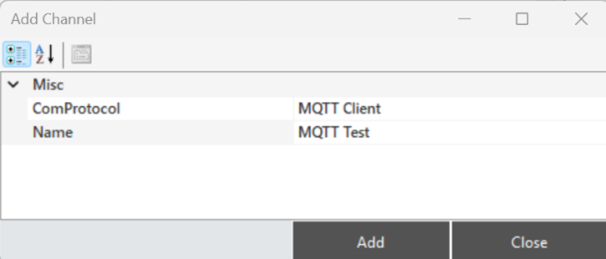
Figure 105 – Creating a MQTT Channel Channel
MQTT Channel Structure
To access and make modifications to the channel information, when a channel is selected, all the details are reflected in the "Channel Information" panel.
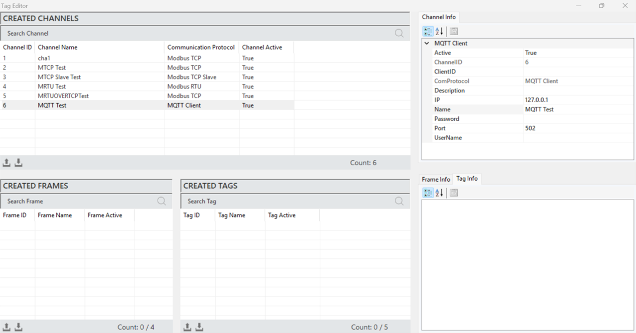
Figure 106 – MQTT Channel Info
The parameter descriptions are presented in the table below.
“Active” | Determines the active/inactive status of the channel. |
“Channel ID” | A unique identification number that defines the channel in a figure. |
“Client ID” | A unique identifier used to identify the client when connecting to the broker |
“Com Protocol” | The communication protocol type. It is defined when creating the channel. |
“Description” | The description of the channel, which is defined based on requirements. |
“IP” | The address of the MQTT Broker on the network it is connected to. |
“Name” | The name of the channel. |
“Password” | The password used to authenticate a secure connection with the broker. |
“Port” | The port information for communication. |
“User Name” | The username used to authenticate a secure connection with the broker. |
Table 21 – MQTT Channel Parameters
MQTT Frame Creation
It is the process of defining a new frame to organize and manage the data structure. To create a frame, a channel must first be created. A channel is selected, and by right-clicking in the “Created Frames” area, the option to add a frame is clicked.
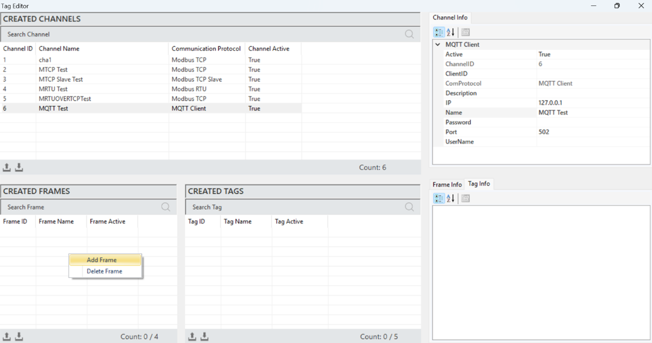
Figure 107 – Creating a MQTT Frame
After entering the frame information in the opened window, click "Add" to create the frame.
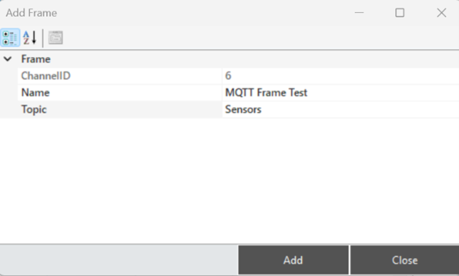
Figure 108 – Creating a MQTT Frame
·
MQTT Frame Structure
When a frame is selected, all information is displayed in the "Frame Information" panel, allowing access to and modifications of the frame details.
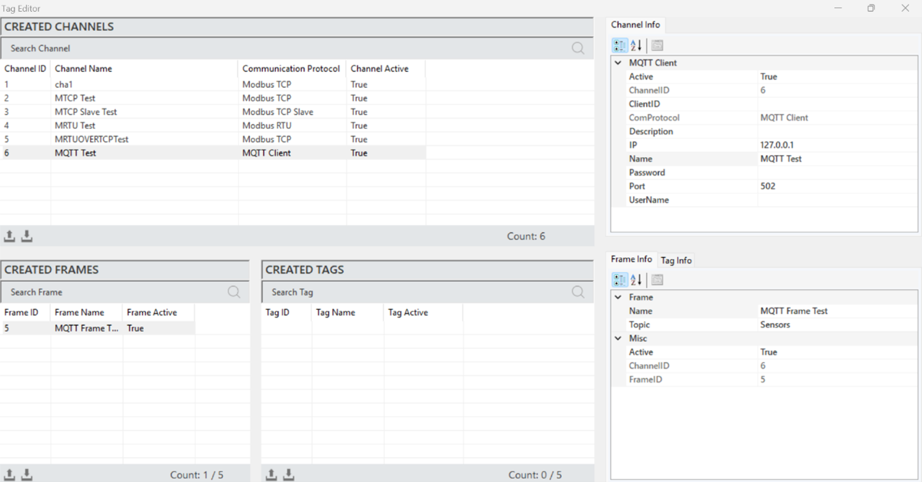
Figure 109 – MQTT Frame Info
The explanations of these parameters are presented in the table below.
“Active” | Determines the active/inactive status of the frame. |
“Channel ID” | The identification number that uniquely defines the channel in a figure. |
“Frame ID” | The Frame ID information. |
“Name” | The name of the frame. |
“Topic” | The topic is a string that defines the subject of a message |
Table 22 – MQTT Frame Parameters
·
MQTT Tag Creation
It is the process of creating a new tag that represents a specific measurement or control data. In order to create a tag, a frame must first be created. A frame is selected, and then right-clicking in the "Created Tags" area and selecting "Add Tag" will initiate the process.
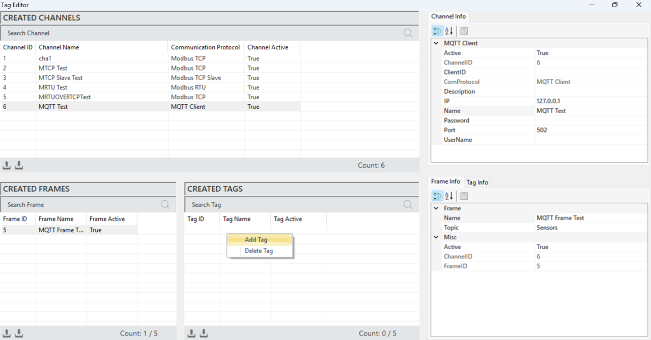
Figure 110 – Creating a MQTT Tag
After entering the tag information in the opened window, click "Add" to create the tag.
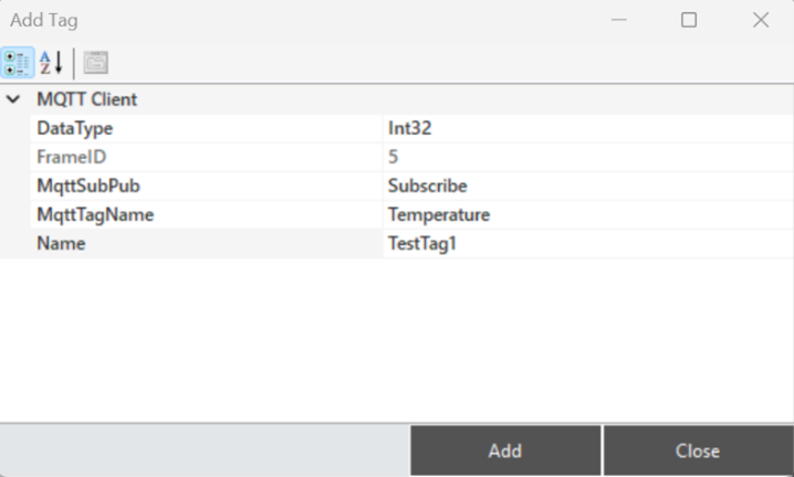
Figure 111 – Creating a MQTT Tag
·
MQTT Tag Structure
When a tag is selected, all information is reflected in the "Tag Information" panel for access and modifications.
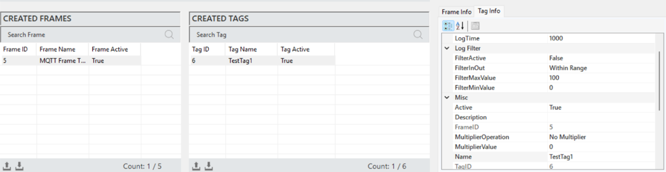
Figure 112 – MQTT Tag Info
The explanations of these parameters are provided in the table below.
“Active” | Determines whether the tag is active or inactive. |
“Description” | Information field for the tag. |
“Frame ID” | Unique identification number of the selected frame. |
“Multiplier Operation” | Defines the mathematical operation. |
“Multiplier Value” | Specifies the value for the operation applied to the tag. |
“Name” | The name of the tag. |
“Tag ID” | A unique identification number that defines the tag in a figure. |
“Log Status” | Determines the log status of the tag data. |
“Log Time” | The time period for data logging, specified in milliseconds. |
“Filter Active” | Enables the filtering function for the tag data logging. |
“FilterInOut” | Defines the filter function for values within or outside a range |
“FilterMaxValue” | Specifies the maximum value for filtering. |
“FilterMinValue” | Specifies the minimum value for filtering. |
“Data Type” | The data type of the tag. |
“MqttSubPub” | Describes the basic MQTT functions for receiving and sending data. |
“MqttTagName” | A name that identifies a specific data point or variable |
Table 23 – MQTT Tag Parameters
4.6 JavaScript Protocol
JavaScript is a high-level programming language used for developing web-based applications and interactive content. Especially running in browser-based environments, JavaScript enables the creation of dynamic web pages and works in an integrated manner with HTML and CSS to manage user interactions. With its event-driven structure, it provides the ability to respond quickly to user actions and facilitates data communication over the network with support for asynchronous programming.
JavaScript Channel Creation
To add a channel in the JavaScript protocol, right-click within the "Created Channels" area and select “Add Channel”.
In the opened window, select the communication protocol as "JavaScript" and enter the channel name to add the new channel.
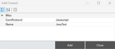
Figure 113 – Creating a Javascript Channel
JavaScript Channel Structure
When a channel is selected, all information is reflected in the "Channel Information" panel to access and make adjustments to the channel details.
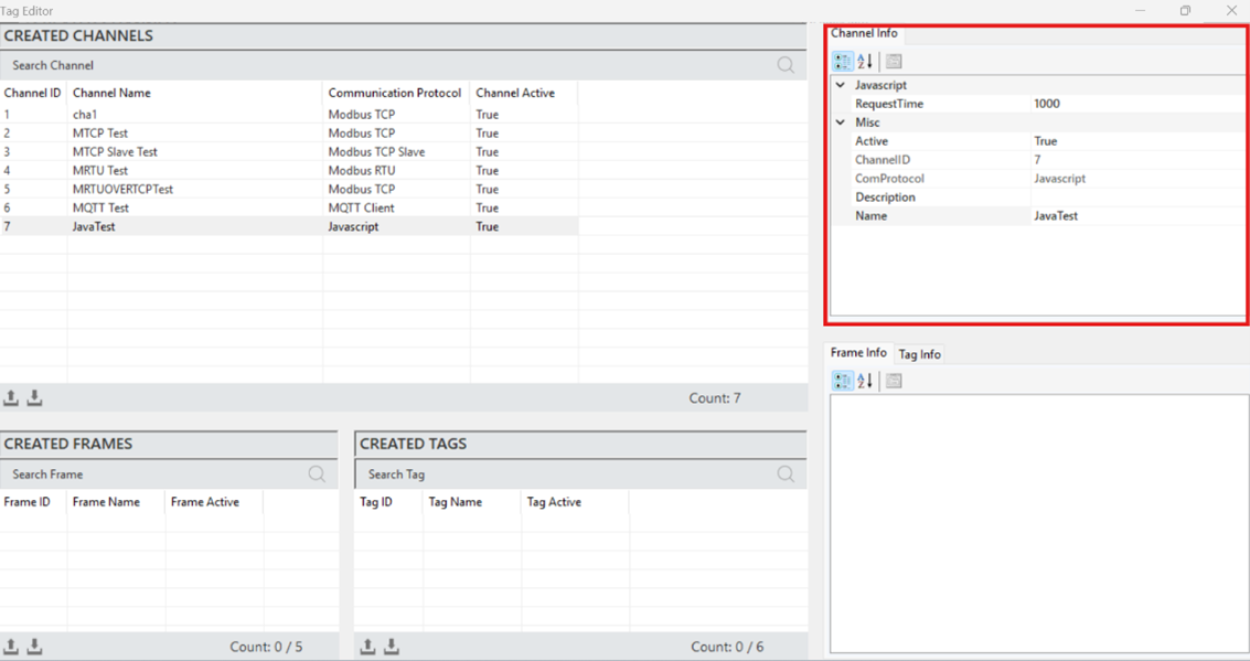
Figure 114 – Javascript Channel Info
The parameter descriptions are presented in the table below.
“Active” | Determines the active/inactive status of the channel. |
“Channel ID” | A unique identification number that defines the channel in a figure. |
“Com Protocol” | The communication protocol type. It is defined when creating the channel. |
“Description” | The description of the channel, which is defined based on requirements. |
“Name” | The name of the channel. |
“Request Time” | The communication data response timeout, specified in milliseconds. |
Table 24 – Javascript Channel Parameter
JavaScript Frame Creation
It is the process of defining a new frame to organize and manage the data structure. To create a frame, a channel must first be created. A channel is selected, and by right-clicking in the "Created Frames" area, the "Add Frame" option is clicked.
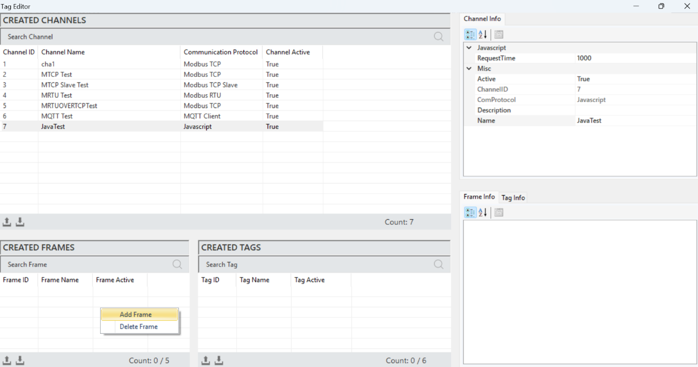
Figure 115 – Creating a Javascript Frame
After entering the information for the frame in the opened window, click "Add" to create the frame.
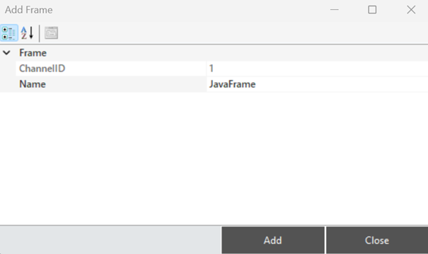
Figure 116 – Creating a Javascript Frame
JavaScript Frame Structure
To access and make adjustments to the frame information, when a frame is selected, all the details are displayed in the "Frame Information" panel.
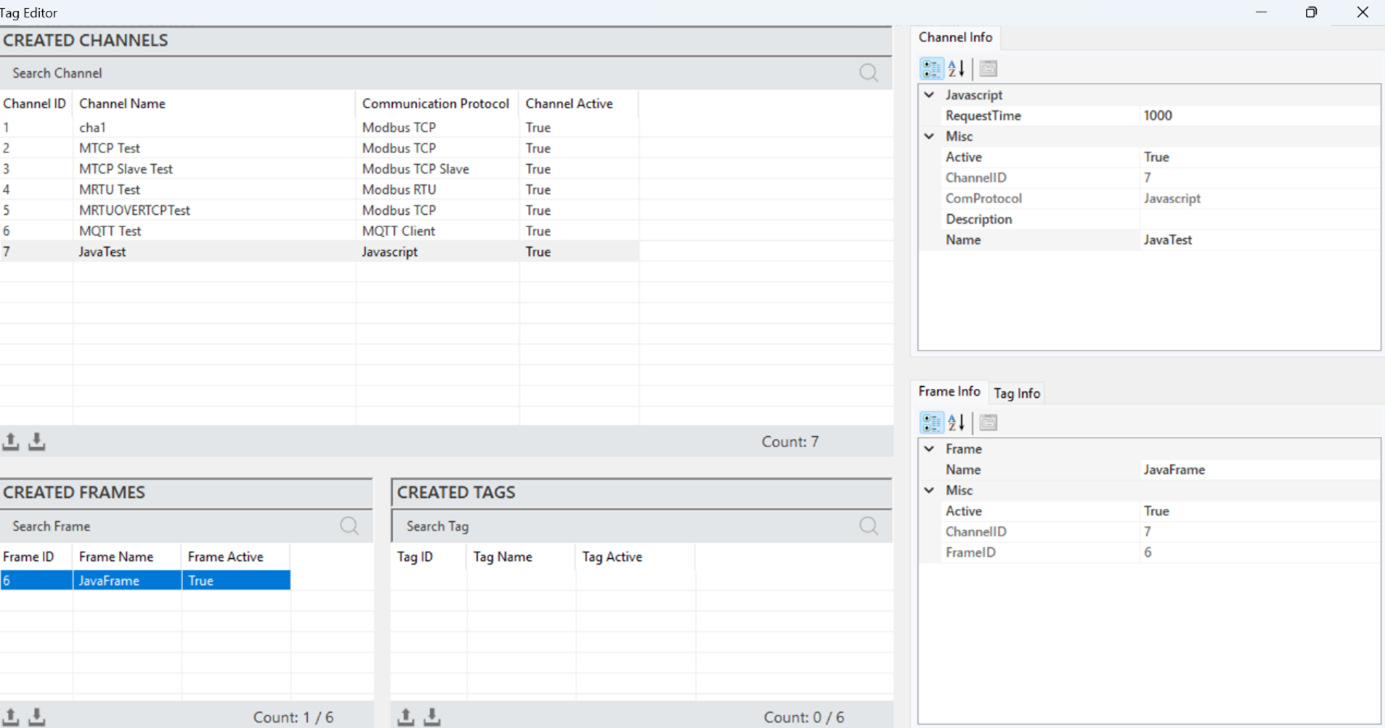
Figure 117 – Javascript Frame Info
The explanations of these parameters are presented in the table below.
“Active” | Determines the active/inactive status of the frame. |
“Channel ID” | The identification number that uniquely defines the channel in a figure. |
“Frame ID” | The Frame ID information. |
“Name” | The name of the frame. |
Table 25 – Javascript Frame Parameters
JavaScript Tag Creation
It is the process of creating a new tag that represents a specific measurement or control data. In order to create a tag, a frame must have already been created. A frame is selected, and then right-clicking in the "Created Tags" area, the option to add a tag is selected.
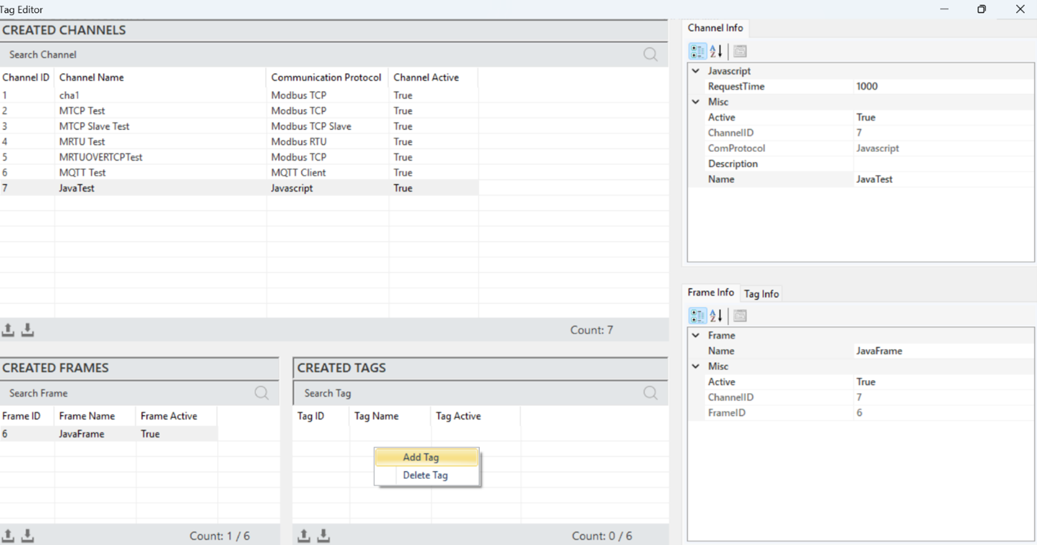
Figure 118 – Creating a Javascript Tag
After entering the tag information in the opened window, click "Add" to create the tag.
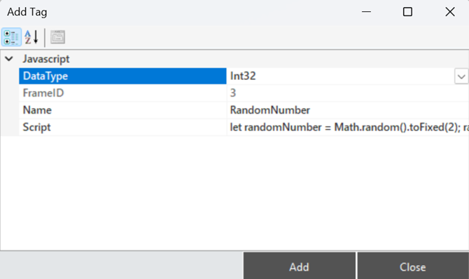
Figure 119 – Creating a Javascript Tag
JavaScript TagStructure
When a tag is selected, all information is reflected in the "Tag Information" panel for access and modifications.
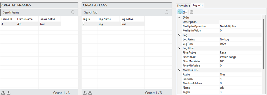
Figure 120 – Javascript Tag Info
The explanations of these parameters are provided in the table below.
"Description" | This is the label information field |
"Multiplier Operation" | Used to perform any mathematical operation on the label data |
"Multiplier Value" | Specifies the value for the operation to be applied to the label |
"Log Status" | Indicates the log status of the label. To activate, set it to “Periodic”, and to deactivate, set it to “No Log” |
"Log Time" | The time duration for recording label data, specified in milliseconds. |
"Filter Active" | If filtering is required while recording label data, this command is activated. |
"FilterInOut" | Defines whether the filter should be applied to values inside or outside the specified range. |
"FilterMaxValue" | Specifies the maximum value in the created filter. |
"FilterMinValue" | Specifies the minimum value in the created filter. |
"Active" | Determines the active/inactive status of the label. |
"Frame ID" | The identification information of the selected frame. |
"ModbusAddress" | Specifies the address for communication of the label. |
"Name" | This is the label name. |
"Tag ID" | The unique identifier number that defines the channel in the figure. |
Table 26 – Javascript Tag Parameters
Javascript Script Input Usage
In the OEE system, JavaScript is used to access and manipulate tag values dynamically. By referencing tag variables (e.g., ${TagID}), scripts can read real-time data from the system, perform calculations, and trigger actions based on specific conditions. This allows flexible and customizable logic within dashboards, alarms, and reports.
To enable usage of a Modbus tag as a variable in JavaScript, a $ symbol is added before the tag.
For example: ${tagID} is displayed as $10.
var a = $10; ->The value is read from tag $10.
$10 = 25;→ A new value is assigned to tag $10.
Each line must be ended with a ‘;’ sign. The last line of the script should include a value to be output.
In the final expression, tags, variables, or static values can be used.
For example:
let randomNumber = Math.random().toFixed(2); randomNumber;
$5=-1;let a=$6;if(a>=200 & a<210){$5=0;}else if(a>=210 & a<220){$5=1;}$5;
When performing numeric operations, Number($tag) should be used to ensure correct data type.
4.6 OPC UA Server Protocol
OPC UA (OLE for Process Control Unified Architecture) Server is a communication protocol used in industrial automation systems to facilitate data exchange. It is designed to enable secure and standardized communication between different devices and systems. Both structured and unstructured data formats are supported, allowing devices and applications to interact seamlessly. The OPC UA Server operates using a client-server architecture and provides capabilities such as data modeling, event handling, and security features.
Unlike other protocols, the OPC UA Server protocol consists only of the channel section.
OPC UA Server Channel Creation
To add a channel in the OPC UA Server protocol, right-click within the "Created Channels" area and select “Add Channel”.
In the opened window, select the communication protocol as " OPC UA Server " and enter the channel name to add the new channel.
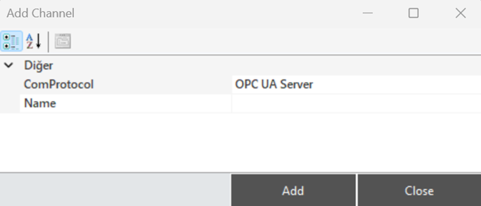
Figure 121 – Creating a OPC UA Channel
OPC UA Server Channel Structure
When a channel is selected, all relevant information is displayed in the "Channel Information" panel, where it can also be edited.
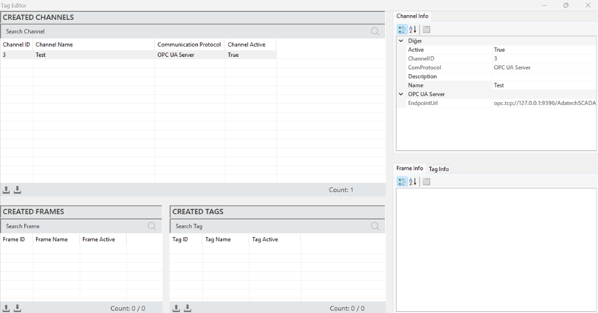
Figure 122 – OPC UA Channel Info
The parameter descriptions are presented in the table below.
“Active” | Determines the active/inactive status of the channel. |
“Channel ID” | A unique identification number that defines the channel in a figure. |
“Com Protocol” | The communication protocol type. It is defined when creating the channel. |
“Description” | The description of the channel, which is defined based on requirements. |
“Name” | The name of the channel. |
“EndPointUrl” | The EndPointUrl is used to establish a connection with the OPC UA server. |
Table 27 – OPC UA Channel Parameters
4.8 Internal Protocol
The Internal module is a communication method specifically developed for the Proveris® OEE system.
Internal Channel Creation
To add a channel in the Internal protocol, right-click in the "Created Channels" area in the Tag Editor and select "Add Channel."

Figure 123 – Creating a Internal Channel
In the opened window, select the communication protocol as " Internal," then specify the channel name to add the new channel.
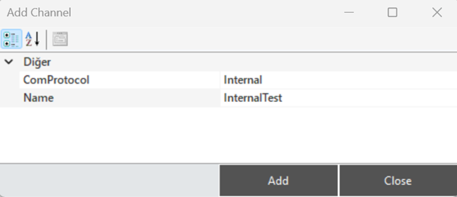
Figure 124 – Creating a Internal Channel
Internal Channel Structure
To access and modify channel information, when a channel is selected, all details are displayed in the "Channel Info" panel.
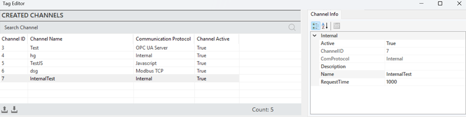
Figure 125 – Internal Channel Info
The parameter descriptions for the channel information are provided in the table below.
“Active” | Determines whether the frame is active or inactive. |
“Channel ID” | A unique identifier for the channel. |
“Com Protocol” | Communication type information. Set when the channel is created. |
“Description” | A description of the channel, defined according to the requirements. |
“Name” | The name of the channel. |
“Request Time” | The communication data response timeout in milliseconds. |
Table 28 – Internal Channel Parameters
Internal Frame Creation
The process of defining a new frame to structure and manage data. To create a frame, a channel must first be created. A channel is selected, and by right-clicking in the "Created Frames" section, the "Add Frame" option is clicked.
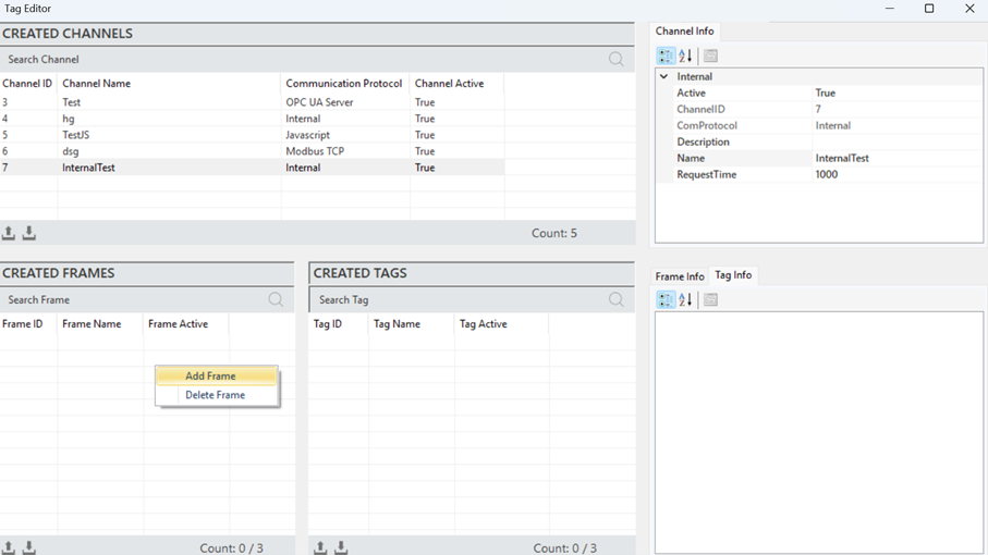
Figure 126 – Internal Frame Info
After entering the frame information in the opened window, click "Add" to create the frame.
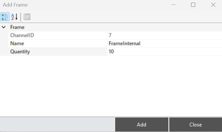
Figure 127 – Creating a Internal Frame
Internal Frame Structure
When a frame is selected, all information is displayed in the "Frame Information" panel for access and editing.
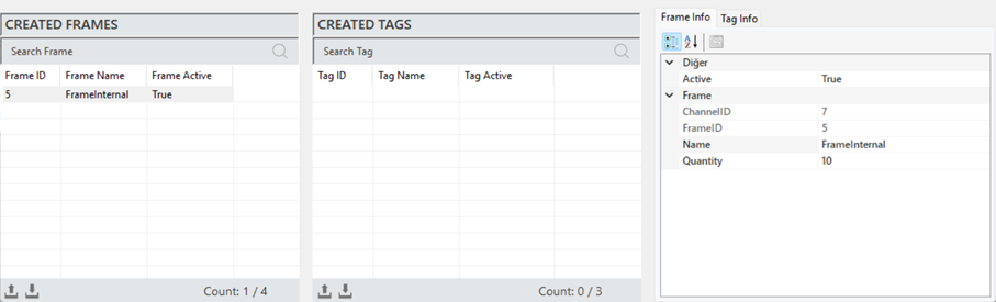
Figure 128 – Internal Frame Info
The explanations of these parameters are provided in the table below.
“Active” | Determines whether the frame is active or inactive. |
“Channel ID” | The unique channel information to which the frame is associated. |
“Frame ID” | The Frame ID information. |
“Name” | The name of the frame. |
“Quantity” | The number of data (tags) in the frame. |
Table 29 – Internal Frame Parameters
·
Internal Tag Creation
The process of creating a new tag that represents a specific measurement or control data. To create a tag, a frame must first be created. Once a frame is selected, right-click on the "Created Tags" area and click on "Add Tag".
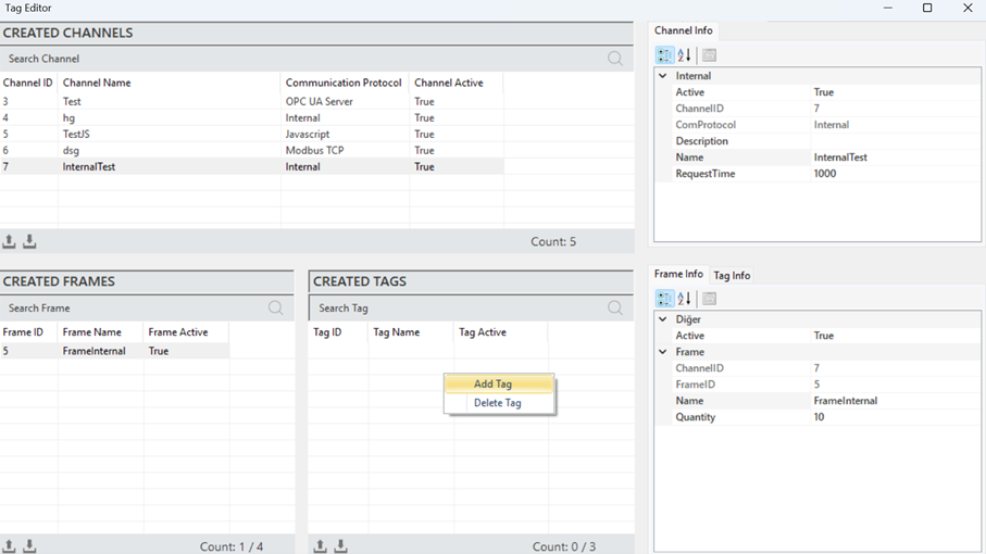
Figure 129 – Creating a Internal Tag
Once the tag information is entered in the opened window, click "Add" to create the tag.
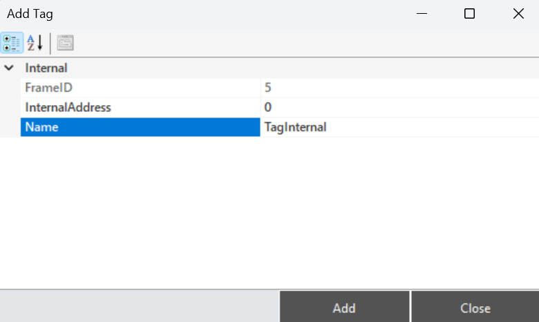
Figure 130 – Creating a Internal Tag
Internal Tag Structure
To access and edit the tag information, when a tag is selected, all the details are displayed in the "Tag Info" panel.
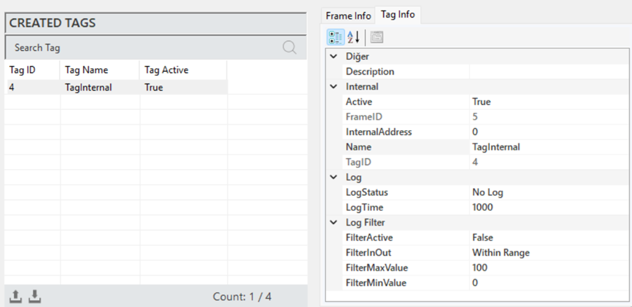
Figure 131 – Internal Tag Info
The explanations of these parameters are presented in the table below.
"Description" | This is the label information field |
"Active" | Determines the active/inactive status of the label. |
"Frame ID" | The identification information of the selected frame. |
"InternalAddress" | Specifies the address for communication of the label. |
"Name" | This is the label name. |
"Tag ID" | The unique identifier number that defines the channel in the figure. |
"Log Status" | Indicates the log status of the label. To activate, set it to “Periodic”, and to deactivate, set it to “No Log” |
"Log Time" | The time duration for recording label data, specified in milliseconds. |
"Filter Active" | If filtering is required while recording label data, this command is activated. |
"FilterInOut" | Defines whether the filter should be applied to values inside or outside the specified range. |
"FilterMaxValue" | Specifies the maximum value in the created filter. |
"FilterMinValue" | Specifies the minimum value in the created filter. |
Table 30 – Internal Tag Parameters